Dual Detector With Transverse Coils

a transverse coil and detector technology, applied in the field of detection of target objects, can solve the problems of insufficient training of operators using these detectors, inability to hold the detector properly, and inability to detect the object properly, so as to reduce false alarms and improve sensitivity

Active Publication Date: 2021-03-18
MANNESCHI ALESSANDRO
View PDF2 Cites 1 Cited by
  • Summary
  • Abstract
  • Description
  • Claims
  • Application Information

AI Technical Summary

Benefits of technology

[0006]An object of the invention is therefore to propose a dual detector comprising a detection head housing an inductive sensor and another sensor, such as a ground-penetrating radar, which is capable of reducing false alarms likely to be generated during scanning of the ground with the detector with the detector while having higher sensitivity.
[0018]at least one of the transmitting coil and the receiving coil has an elongated shape in a given direction, the transmitting antenna and the receiving antenna also having an elongated shape in said direction so as to maximize their radiating surface.

Problems solved by technology

In use, the Applicant has however noticed that the ground was not neutral from an electromagnetic point of view and can therefore disturb the coupling between the windings.
In addition, the ground is rarely uniformly magnetic so that, during the scanning of the ground with the detector by an operator, the detected signal can vary only due to the presence of metal debris or to the very composition of the ground, or even trigger false alarms.
In addition, the operators using these detectors may be inadequately trained and may not hold the detector properly or perform an inappropriate scanning motion.
The detection head can then form a lateral angle with the ground, so that one of the coils is closer to the ground than the other of the coils, which creates a strong modulation of the signal and therefore risks triggering false alarms.
And even if the operator were well trained and tried to keep the detection head substantially parallel to the ground at any point in the scanning motion, he cannot locally modify its inclination to take into account the unevenness in the ground.
In order to overcome these difficulties, manufacturers tend to reduce the sensitivity of these detectors.
The risk, however, is that it will no longer be able to detect targets buried in the ground and therefore put the lives of the operators in danger.

Method used


Image

  • Dual Detector With Transverse Coils
  • Dual Detector With Transverse Coils
  • Dual Detector With Transverse Coils

Examples


Embodiment Construction

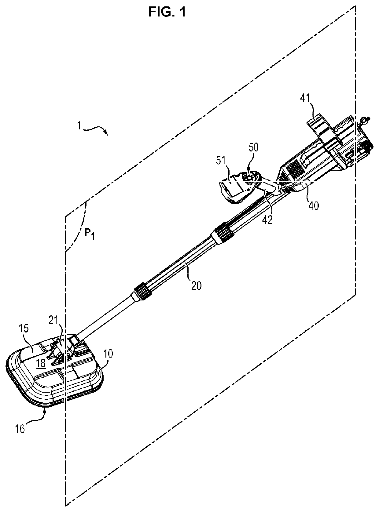
[0032]A dual detector 1 according to the invention comprises a detection head 10 fastened to a handle 20 by means of a mechanical link 21.

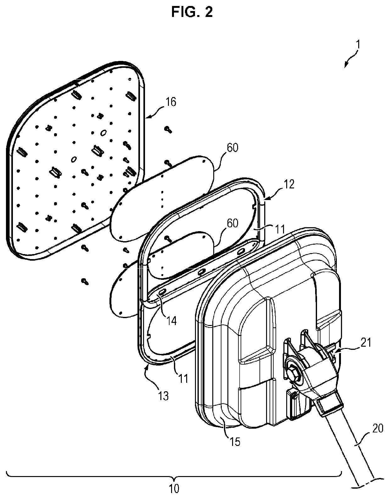
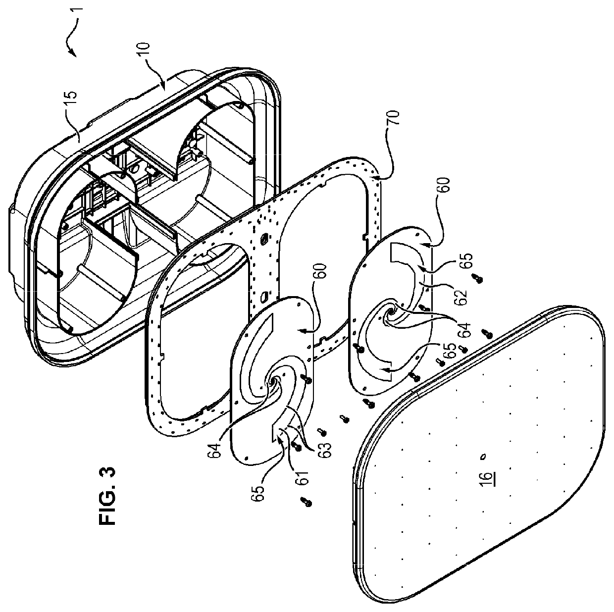
[0033]The detection head 10 corresponds to the part intended to come close to the ground in order to detect target products. To this end, it comprises:[0034]an enclosure 18 including a cover 15 on which is fastened the mechanical link and a base 16, opposite the cover 15 and configured to face the ground to be probed,[0035]an inductive sensor 12, 13, fixedly mounted in the enclosure 18, and[0036]a ground-penetrating radar 60, fixedly mounted in the enclosure 18.

[0037]What is meant here by “fixedly mounted” is that, under normal operating conditions, the inductive sensor 12, 13 and the radar 60 are immobile relative to the enclosure 18. The inductive sensor 12, 13 and the radar 60 can either be removed without being damaged, for example for maintenance operations, or on the contrary be fastened permanently in the enclosure 18.

[0038]The inductive se...


PUM


Abstract

The invention relates to a dual detector with a detection head (10), comprising:—a platform (11) and—an induction sensor fastened to the platform (11) and comprising a transmitter coil (12) and a receiver coil (13), the transmitter coil (12) and the receiver coil (13) each forming a loop, the loop of the transmitter coil (12) overlapping the loop of the receiver coil (13) at least partially so as to form a coupling zone (14), the coupling zone (14) being elongated in a first longitudinal direction defining a first axis (X1), the handle (20) extending in a plan (P1) normal to the platform (11) and the first axis (X1) of the coupling zone (14) being transverse to this plane (X1).

Description

FIELD OF THE INVENTION[0001]The invention relates to the field of detecting target objects, and more particularly the detection of explosive charges such as land mines buried in the ground.TECHNICAL BACKGROUND[0002]In order to detect explosive charges, it is known to use dual technology detectors (“dual detectors”) comprising a detection head housing an inductive sensor and a ground-penetrating radar, insofar as these technologies are complementary as regards the types of materials detected (metals for the inductive sensor vs. differences in dielectric constants of the materials and relative position for the radar).[0003]In use, the Applicant has however noticed that the ground was not neutral from an electromagnetic point of view and can therefore disturb the coupling between the windings. In addition, the ground is rarely uniformly magnetic so that, during the scanning of the ground with the detector by an operator, the detected signal can vary only due to the presence of metal de...

Claims


Application Information

Patent Timeline
Patent Type & Authority Applications(United States)
IPC IPC(8): F41H11/136G01S13/86G01S13/88G01V3/10G01V3/165H04B5/00
CPCF41H11/136G01S13/86H04B5/0081G01V3/105G01V3/165G01S13/885G01V3/10G01V3/12H04B5/0075G01V3/16G01S13/89G01S13/0209G01V8/005G01V3/15
Inventor MANNESCHI, ALESSANDRO
Owner MANNESCHI ALESSANDRO
Why Eureka
Try Eureka