Method of distinguishing, from a moving platform, stationary objects from moving objects

a technology of moving platforms and objects, applied in the field of sensing or detecting objects, can solve the problems of sudden speed change of traffic ahead, blind spot, dangerous distraction of driver's attention from the front to make shoulder checks, etc., and achieve the effect of reducing false alarms

Inactive Publication Date: 2009-06-16
1138037 ONTARIO ALIRT
View PDF9 Cites 1 Cited by
  • Summary
  • Abstract
  • Description
  • Claims
  • Application Information

AI Technical Summary

Benefits of technology

[0006]The present invention is directed to an inexpensive yet elegant solution for reducing false alarms arising from stationary objects in a target area of a system with two or more sensors. The present invention reduces such false alarms, even where the detectors are not strictly seeing the same perspective of the target area or the vehicle has exhibited some roll, pitch, or other movement during the sensing period that has caused the detectors to see the target area from different angles.

Problems solved by technology

The blind spot exists due to the limited scope of view provided by conventional systems of rear and side view mirrors.
Often this is done under pressure and is subject to frequent misjudgments and often enough a shoulder check fails to reveal a vehicle in the blind spot.
The problem is compounded in heavy traffic where numerous shoulder checks may be required before being able to find an opening to change lanes.
In heavy traffic the likelihood of a sudden speed change of the traffic ahead is also increased so having the driver's attention diverted from the front to make shoulder checks is dangerous.
However, parallel lines of sight are not always possible or desirable.
Small changes in the mounting can result in misalignments and non-parallel sight lines.
The host vehicle itself may exhibit roll, pitch, or other movement during the time between when the readings are taken by the first detector and the second detector, resulting in the two detectors not detecting exactly the same field of view of the target area.
The stationary target area may include an abrupt field change, from near to far, such as an end of a guardrail, which can exacerbate differences from non-parallel fields of view, and which can lead to a false alarm.

Method used


Image

  • Method of distinguishing, from a moving platform, stationary objects from moving objects
  • Method of distinguishing, from a moving platform, stationary objects from moving objects
  • Method of distinguishing, from a moving platform, stationary objects from moving objects

Examples


Embodiment Construction

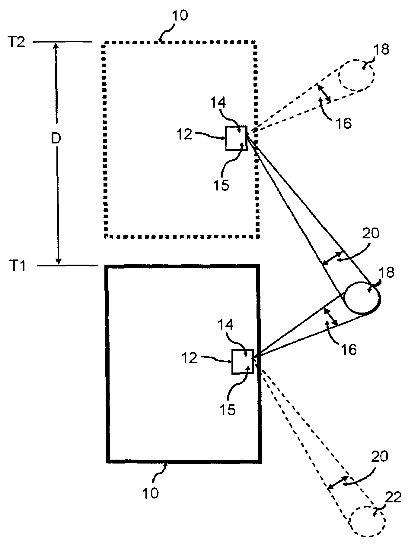
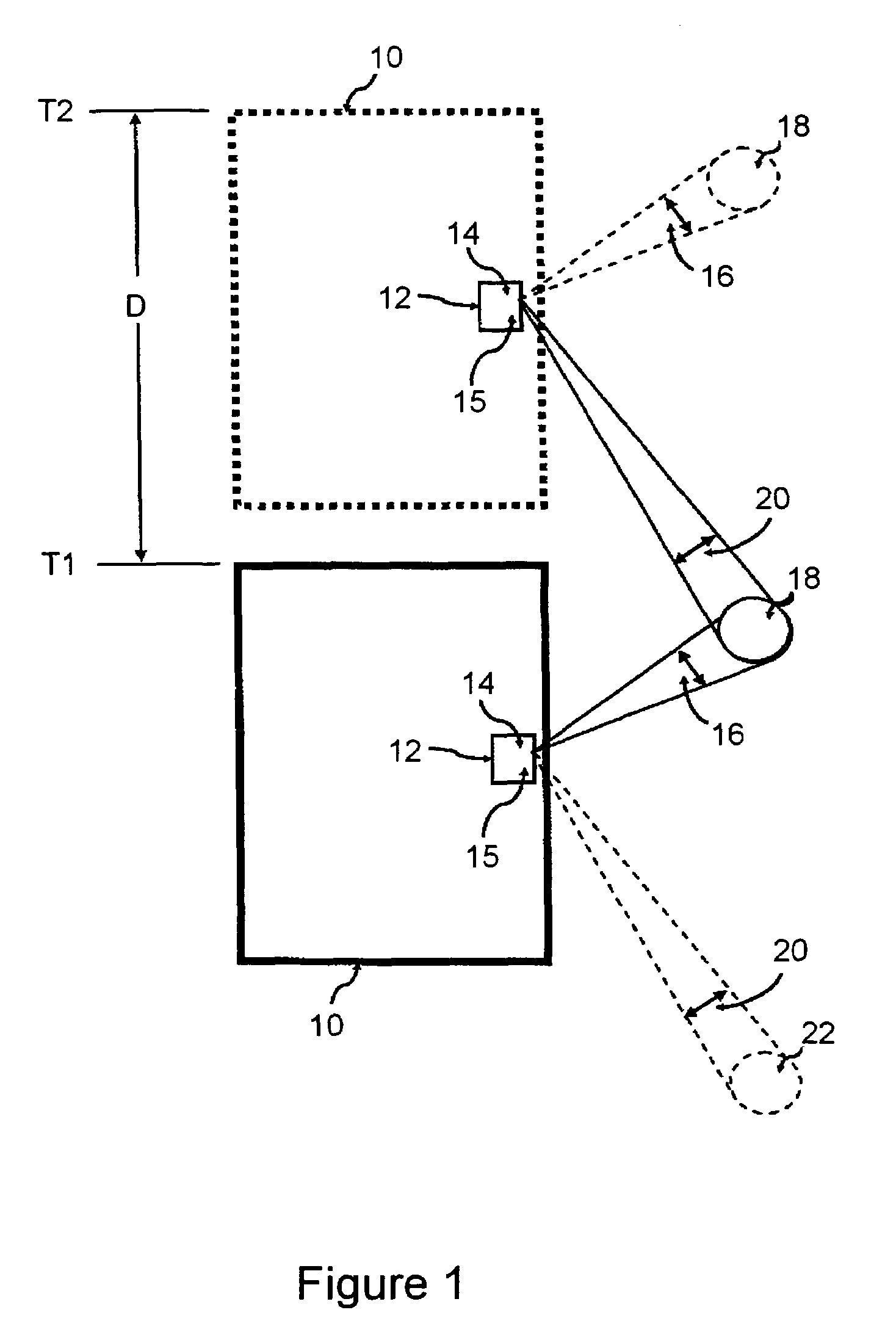
[0024]In this description of the invention, the following terms shall have the following meanings:[0025]The term moving platform shall mean any type of vehicle or other mobile device which moves, whether through the use of wheels or otherwise. The most common type of moving platform is considered to be motor vehicles such as cars, trucks, busses and the like, but the present invention can also be applied to many other types of moving devices or machines. The term moving platform is intended to comprehend all such devices.[0026]The term detector means any type of device that can detect a feature or quality of a sensed or target area. The term detector includes active detectors, which send out a signal whose reflection is measured, as well as passive detectors which merely sense an amount of a given property or thing, for example, infrared or IR detectors. The most preferred form of detector is a passive infrared detector, for various reasons such as cost of sensor, ease of use and re...


PUM


Abstract

A method of distinguishing, from a moving platform, stationary objects from moving objects. The method includes using a first detector mounted to the moving platform to obtain at least a first reading from a target area, advancing the moving platform relative to the target area and using a second detector mounted to said moving platform to obtain at least a second reading from said target area. Then, the method includes comparing said first and second readings for at least two different time intervals to distinguish moving objects from stationary objects.

Description

CROSS REFERENCE TO RELATED APPLICATION[0001]This application claims priority to U.S. Provisional Patent Application No. 60 / 696,971, filed Jul. 6, 2005, and is incorporated by reference herein for all purposes.FIELD OF THE INVENTION[0002]This invention relates generally to the field of sensing or detecting objects, and more particularly to detecting objects from a moving platform, such as a vehicle. Most particularly this invention relates to a method of distinguishing moving objects from stationary objects for the purpose of, for example, blind spot detection.BACKGROUND OF THE INVENTION[0003]Much effort has recently been directed to developing safety systems which assist vehicle drivers by detecting objects located in the so-called blind spot of the driver's vision or field of view. The blind spot exists due to the limited scope of view provided by conventional systems of rear and side view mirrors. The existence of the blind spot is well known and requires a practice known as the s...

Claims


Application Information

Patent Timeline
Patent Type & Authority Patents(United States)
IPC IPC(8): B60Q1/00B60R99/00
CPCG01P3/68G01S11/12G06T7/20G01S13/536
Inventor PATCHELL, JOHN W.
Owner 1138037 ONTARIO ALIRT
Why Eureka
Try Eureka