Wall clamping junction box

a junction box and wall clamping technology, applied in the direction of electrical appliances, etc., can solve the problems of damage to the junction box, labor-intensive and expensive process, and difficulty in accessing the building frame without first removing the wall or ceiling surface,

Active Publication Date: 2017-06-06
DMF
View PDF3 Cites 59 Cited by
  • Summary
  • Abstract
  • Description
  • Claims
  • Application Information

AI Technical Summary

Benefits of technology

[0008]This invention provides an improved electrical junction box and lamp housing which is easier to install in remodel or retrofit work.
[0011]A clamping bracket is slidable in each of the slots and a pair of clamping screws each threaded to one bracket is captive to the box. Each screw is rotatable for drawing a corresponding clamping bracket along its slot from an initial elevated position towards the corresponding outer flange, such that a wall edge adjacent to the box side walls is clamped between the brackets and the outer flanges thereby fastening the box to the wall.

Problems solved by technology

In remodel construction requiring installation of junction boxes, however, it is difficult to access the building frame without removing the wall or ceiling surface first, i.e. tearing off dry wall sheet and the like.
This is a labor intensive and expensive process.
Many of these products are designed for a single installation, damaging both the wall and the junction box if removed.

Method used


Image

  • Wall clamping junction box
  • Wall clamping junction box
  • Wall clamping junction box

Examples


Embodiment Construction

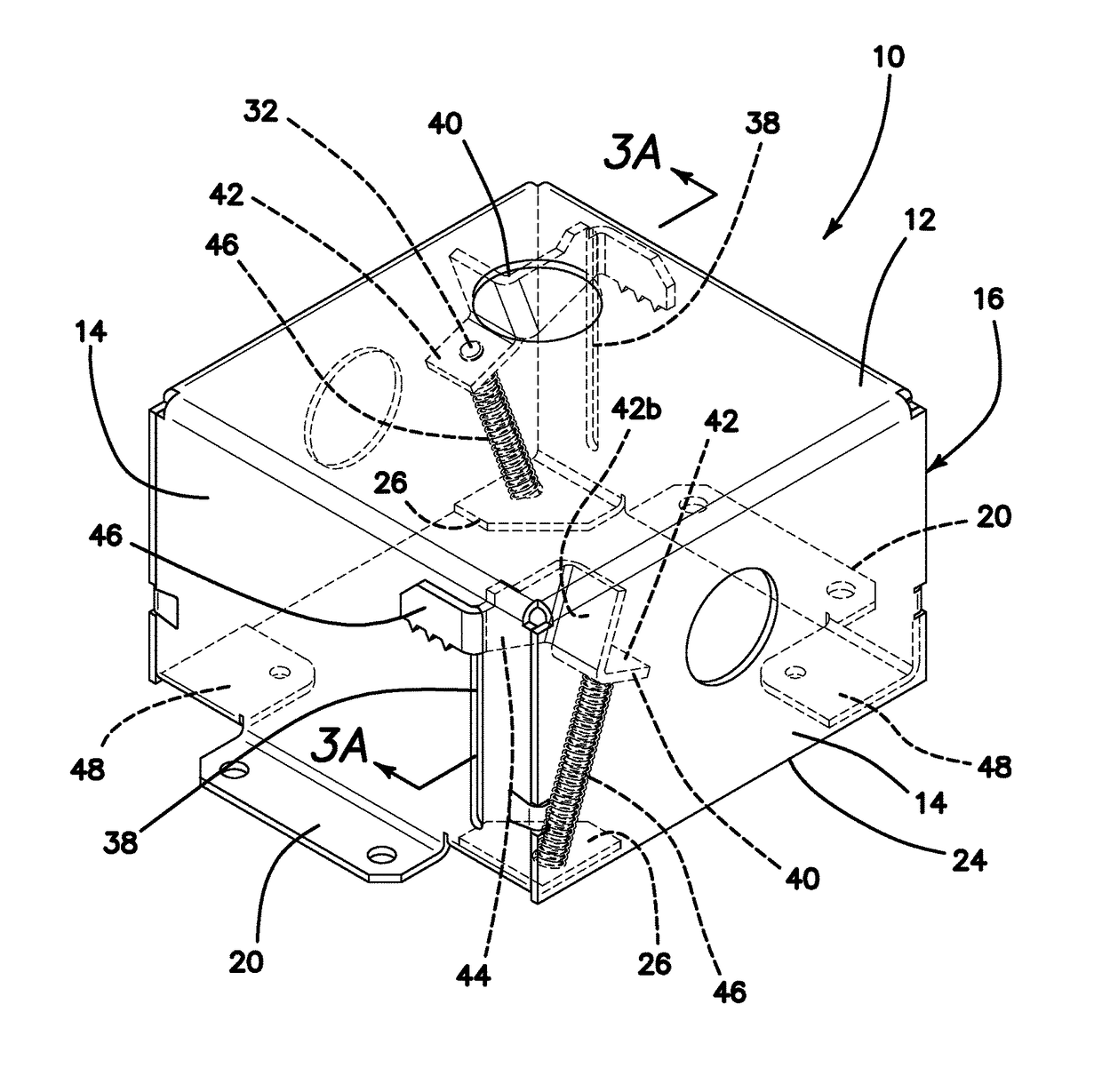
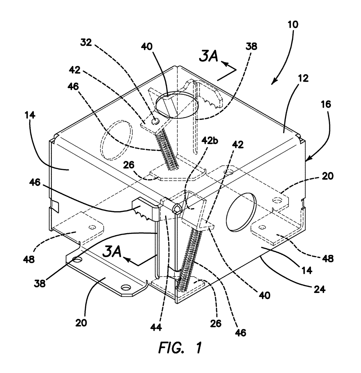
[0024]With reference to the accompanying drawings wherein like elements are designated by like numerals, FIG. 1 shows a wall clamping junction box generally designated by numeral 10 which has a rectangular top wall 12 and four side walls 14 defining a generally rectangular enclosure 16 with an open bottom 18 bounded by the four side walls 14. The enclosure 16 may be of sheet metal similar to electrical junction boxes currently in general use. A number of knockout openings 22 are provided in top wall 12 and side walls 14, which may be individually opened as needed to receive electrical conduit and admit electrical conductors into box 10.

[0025]A pair of rigid clamping flanges 20 extend horizontally away from lower edges 24 of opposite side walls 14. A pair of screw bearing flanges 26 are supported in diagonally opposed corners between contiguous side walls 14. Each screw bearing flange 26 is perforated with a screw hole 28 sized to loosely pass the threaded shaft 32 of a machine screw...


PUM


Abstract

An enclosure such as an electrical junction box has fixed clamping flanges exterior to the enclosure, screws rotatable relative to the enclosure and operative for drawing clamping brackets from an initial elevated position towards the clamping flanges for clamping the edges of an opening cut in drywall or the like, thereby to fasten the enclosure inside a wall or ceiling. The clamping brackets are initially retracted in the enclosure and rotation of the screws releases the brackets to an extended clamping position relative to the clamping flanges.

Description

FIELD[0001]This invention relates to junction boxes and housings used in residential and commercial construction to enclose electrical wiring and recessed light fixtures against fire and electrical hazards.BACKGROUND[0002]Municipal construction codes generally require that electrical wiring, particularly in-wall wiring, be contained in fire resistant protective conduit, usually metal conduit. Where two or more electrical wires are connected the outer protective conduit must be cut or terminated in order to join the interior electrical conductors to each other. The resulting gap in protective conduit is bridged with a junction box which provides continuity of enclosure between multiple wire conduits. The ends of metal conduits are joined to the walls of the junction box while electrical wires in the conduits enter through openings in the box walls into the junction box where the wires may be interconnected with each other, e.g. with electrical nut fasteners. In the event of an electr...

Claims


Application Information

Patent Timeline
Patent Type & Authority Patents(United States)
IPC IPC(8): H02G3/12
CPCH02G3/121H02G3/123
Inventor LEE, NATHAN
Owner DMF
Why Eureka
Try Eureka