Timing belt with a belt lock

a technology of belt lock and belt, which is applied in the direction of belt fastening, driving belt, chain element, etc., can solve the problems of unacceptable elongation of belt, belt is therefore slightly too short in the area of lock, etc., and achieves exceptional versatility in shaping, low cost, and high elasticity

Active Publication Date: 2017-06-20
SIG TECH AG
View PDF47 Cites 3 Cited by
  • Summary
  • Abstract
  • Description
  • Claims
  • Application Information

AI Technical Summary

Benefits of technology

[0027]Finally, in a further refinement of the invention it is suggested that the timing belt be made from plastic and comprise tension elements of metal, particularly steel. Plastics are particularly suitable due to their low cost, high elasticity and their exceptional versatility in terms of shaping. Tension elements of steel are notable for their very high tensile strength. The properties of both materials may be combined advantageously by embedding tension elements of steel in the plastic. Alternatively, the tension elements may be made from any other material that is capable of withstanding a tensile load, for example glass fibres (Kevlar), carbon fibres or textile fibres.

Problems solved by technology

The offset results in undersizing; when not under tension, the belt is therefore slightly too short in the area of the lock.
In known belts, this tension leads to unacceptable elongation of the belt in the area of the belt lock.

Method used


Image

  • Timing belt with a belt lock
  • Timing belt with a belt lock
  • Timing belt with a belt lock

Examples


Embodiment Construction

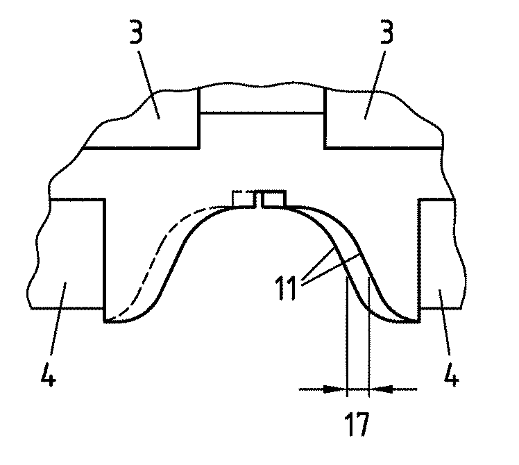
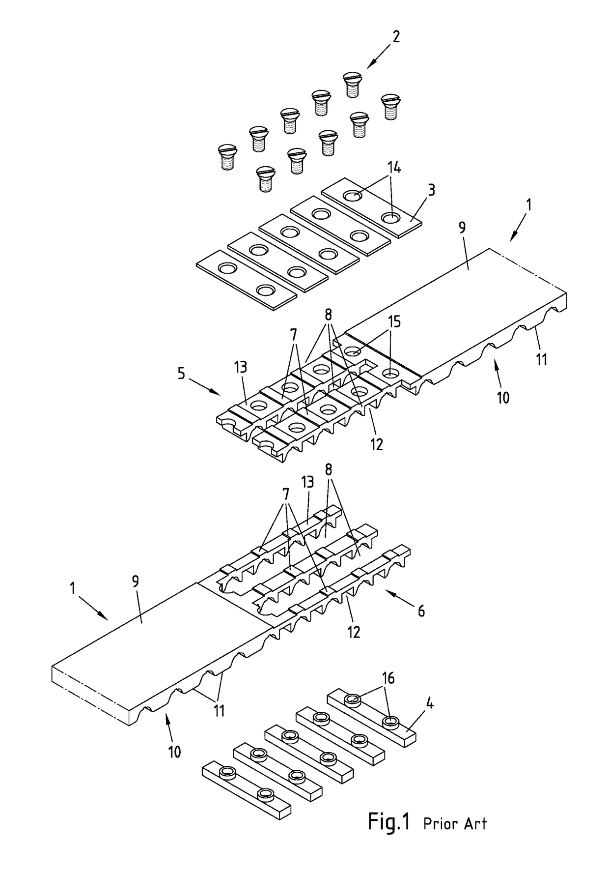
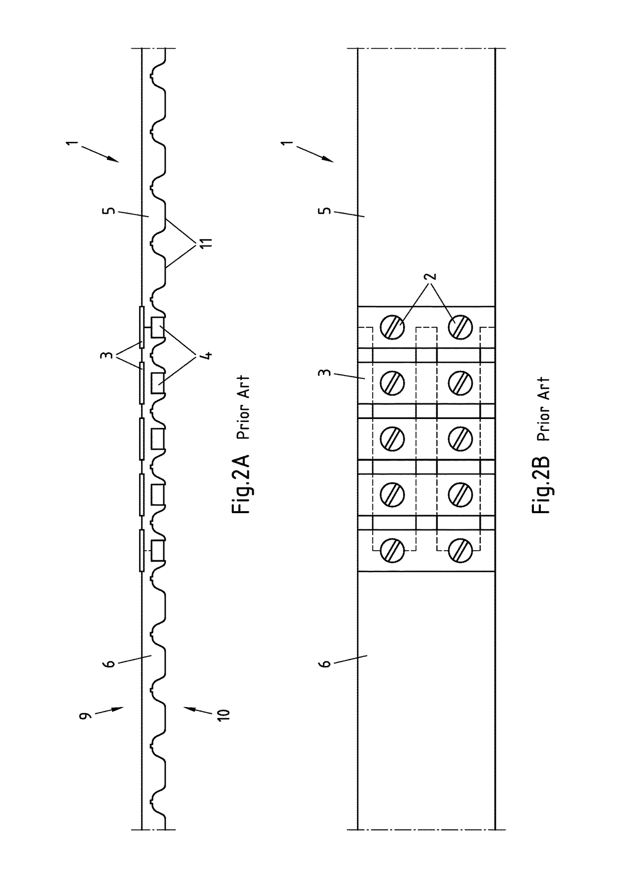
[0042]FIG. 1 shows a perspective view of a timing belt 1 known from the prior art, having connecting elements and in the unmounted condition. The connecting elements are screws 2, back panels 3 and inserts 4. The timing belt 1 shown in FIG. 1 is a toothed belt with a first end 5 and a second end 6.

[0043]The first end 5 of timing belt 1 has two tines 7 and three recesses 8. One of the recesses 8 is arranged between the two tines 7, while the other two recesses 8 are arranged to one side of tines 7. In the same way, second end 6 of timing belt 1 has three tines 7 and two recesses 8, wherein the two recesses 8 are arranged between the three tines 7 in the manner shown in FIG. 1.

[0044]First end 5 and second end 6 of timing belt 1 are shaped so as to complement one another. This means that tines 7 of first end 5 fit exactly into recesses 8 on second end 6. In the same way tines 7 of second end 6 fit perfectly in recesses 8 on first end 5. When the two ends 5 and 6 are pushed into one ano...


PUM


Abstract

The application describes and illustrates a timing belt, particularly a toothed belt, having a first end, a second end, a rear side, a front side, and having a plurality of teeth arranged on the rear side and/or the front side, wherein the first end has at least one cutaway, wherein the second end has at least one tine that is insertable into the cutaway, and wherein the first end and the second end are detachably connectable to each other and the teeth of the first end have an offset relative to the teeth of the second end in the connected condition under no tension.

Description

CROSS-REFERENCE TO RELATED APPLICATIONS[0001]This application is the United States national phase of International Application No. PCT / EP2014 / 066396 filed Jul. 30, 2014, and claims priority to German Patent Application No. 10 2013 110 027.9 filed Sep. 12, 2013, the disclosures of which are hereby incorporated in their entirety by reference.BACKGROUND OF THE INVENTION[0002]Field of the Invention[0003]The invention relates to a timing belt, particularly a toothed belt, having a first end, a second end, a rear side, a front side, and having a plurality of teeth arranged on the rear side and / or the front side, wherein the first end has at least one cutaway, wherein the second end has at least one tine that is insertable into the cutaway, and wherein the first end and the second end are detachably connectable to each other by connecting means.[0004]Timing belts and particularly toothed belts are known in many different designs. Toothed belts are positive locking driving or transporting e...

Claims


Application Information

Patent Timeline
Patent Type & Authority Patents(United States)
IPC IPC(8): F16G1/28F16G15/00F16G3/00F16G3/08F16G5/20F16G13/02
CPCF16G3/08F16G1/28
Inventor VOLLBARTH, JURGENVON BIRGELEN, BERNDKLAUS, MARKUS
Owner SIG TECH AG
Why Eureka
Try Eureka