Linear motor with electromagnetically actuated spring mover

a technology of spring mover and linear motor, which is applied in the direction of positive displacement liquid engine, dynamo-electric components, dynamo-electric machines, etc., can solve the problems of reducing affecting the resonant frequency of the linear motor, and the relative cost of components, so as to reduce the reluctance of the magnetic field.

Active Publication Date: 2017-06-20
HAIER US APPLIANCE SOLUTIONS INC
View PDF6 Cites 3 Cited by
  • Summary
  • Abstract
  • Description
  • Claims
  • Application Information

AI Technical Summary

Benefits of technology

[0009]Another aspect of the present disclosure is directed to a linear motor. The linear motor includes a spring having a plurality of coils. A plurality of air gaps respectively exist between the plurality of coils when the spring is in an uncompressed position. The linear motor includes a stator surrounding at least a portion of the spring. The linear motor includes a plurality of windings respectively positioned within a plurality of winding cavities spaced along a longitudinal axis of the stator. Application of electrical energy to the plurality of windings generates a magnetic field that flows through one or more of the plurality of coils. The flow of the magnetic field through the one or more of the plurality of coils actuates the spring towards a compressed position in which the plurality of air gaps are reduced, thereby reducing the reluctance experienced by the magnetic field.

Problems solved by technology

However, both of the above noted designs require the linear motor to include one or more permanent magnets, which are relatively expensive components.
Further, certain permanent magnets can be formed from rare earth elements or other materials of limited global quantity or commercial availability.
As such, high quality permanent magnets can significantly contribute to the cost associated with producing a linear motor.

Method used


Image

  • Linear motor with electromagnetically actuated spring mover
  • Linear motor with electromagnetically actuated spring mover
  • Linear motor with electromagnetically actuated spring mover

Examples


Embodiment Construction

[0017]Reference now will be made in detail to embodiments of the invention, one or more examples of which are illustrated in the drawings. Each example is provided by way of explanation of the invention, not limitation of the invention. In fact, it will be apparent to those skilled in the art that various modifications and variations can be made in the present invention without departing from the scope or spirit of the invention. For instance, features illustrated or described as part of one embodiment can be used with another embodiment to yield a still further embodiment. Thus, it is intended that the present invention covers such modifications and variations as come within the scope of the appended claims and their equivalents.

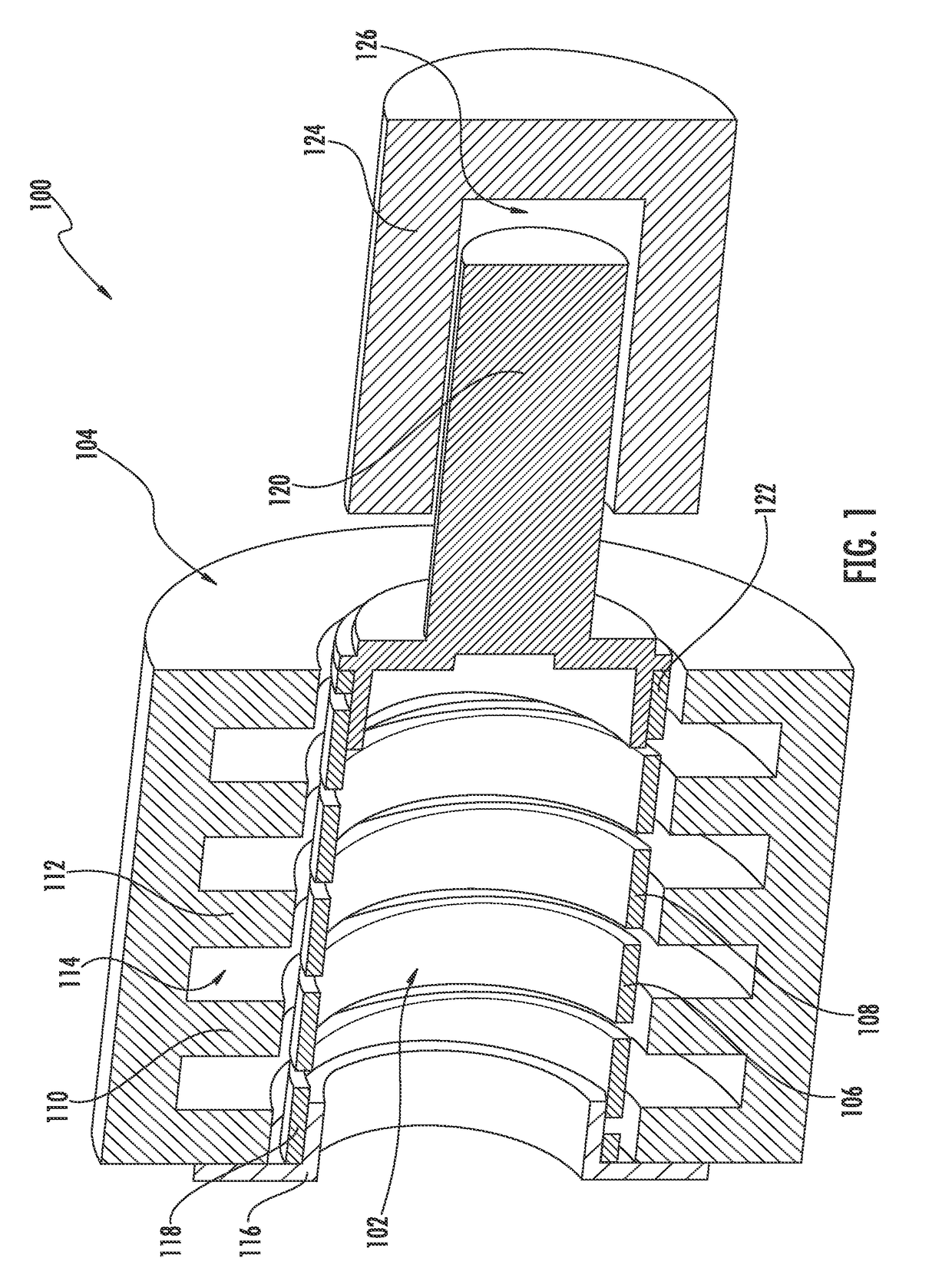
[0018]With reference now to the FIGS., example embodiments of the present disclosure will be discussed in further detail. FIG. 1 depicts a cross-sectional view of an example linear motor 100 according to an example embodiment of the present disclosure.

[0019...


PUM


Abstract

Reluctance-based resonant linear motors and methods of operation are provided. An example linear motor includes a spring having a plurality of coils. The linear motor includes a stator coaxially surrounding at least a portion of the spring. The stator includes a plurality of teeth. The linear motor includes a plurality of windings respectively positioned within a plurality of winding cavities respectively formed by the plurality of teeth. The application of electrical energy to the plurality of windings generates a magnetic field that flows through one or more of the coils of the spring. The flow of the magnetic field through the one or more coils of the spring causes the spring to actuate towards a compressed position. An example method includes periodically applying electrical energy to the plurality of windings such that the spring oscillates at a resonance frequency associated with the linear motor.

Description

FIELD OF THE INVENTION[0001]The present disclosure relates generally to linear motors. More particularly, the present disclosure is directed to reluctance-based resonant linear motors.BACKGROUND OF THE INVENTION[0002]Linear motors are a form of electric motors in which electrical energy is used to drive a motor component in one or more linear directions. For example, many existing linear motors generate a magnetic field which influences one or more permanent magnets to move in the linear directions.[0003]Alternatively, the permanent magnets can be fixed in a certain position and the component that generates the magnetic field (e.g. an armature including windings) can move as a result of the magnetic forces.[0004]However, both of the above noted designs require the linear motor to include one or more permanent magnets, which are relatively expensive components. For example, various industrial processes must be performed to create and shape permanent magnets of sufficient strength and...

Claims


Application Information

Patent Timeline
Patent Type & Authority Patents(United States)
IPC IPC(8): H02K33/02F04B17/04H02K33/04F04B17/03H02K33/00H02K41/00H02K41/02
CPCH02K33/02F04B17/03F04B17/04H02K33/00H02K33/04H02K41/00H02K41/02
Inventor FILIPPA, MARIANO PABLO
Owner HAIER US APPLIANCE SOLUTIONS INC
Why Eureka
Try Eureka