Electromagnetic brake for a power transmission assembly

a technology of power transmission assembly and electromagnetic brake, which is applied in the direction of non-mechanical actuated clutches, clutches, actuators, etc., can solve the problems of limited brake torque that can be provided by the brake, limited magnetic attraction between the brake plate and the armature, etc., to reduce the magnetic reluctance of the electromagnetic circuit and increase the magnetic attraction

Active Publication Date: 2018-01-23
WARNER ELECTRIC TECH
View PDF21 Cites 2 Cited by
  • Summary
  • Abstract
  • Description
  • Claims
  • Application Information

AI Technical Summary

Benefits of technology

[0006]This disclosure relates to an electromagnetic brake for a power transmission assembly. In particular, the disclosure relates to an electromagnetic brake having a hub that is configured to form a part of an electromagnetic circuit in the brake to reduce magnetic reluctance in the electromagnetic circuit and increase the magnetic attraction between an armature and a brake plate within the brake.
[0009]An electromagnetic brake for a power transmission assembly in accordance with the present teachings is advantageous relative to conventional electromagnetic brakes. In particular, the hub of the brake is configured in a such a way that it forms a part of the electromagnetic circuit of the brake. The configuration reduces magnetic reluctance in the electromagnetic circuit and increase the magnetic attraction between an armature and a brake plate within the brake thereby increasing the available braking torque.

Problems solved by technology

The magnetic attraction between the brake plate and armature may be limited by a relatively high magnetic reluctance in the electromagnetic circuit.
As a result, the brake torque that can be provided by the brake may also be limited.

Method used


Image

  • Electromagnetic brake for a power transmission assembly
  • Electromagnetic brake for a power transmission assembly
  • Electromagnetic brake for a power transmission assembly

Examples


Embodiment Construction

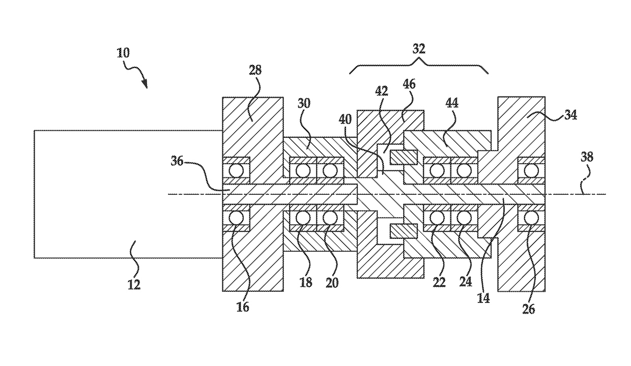
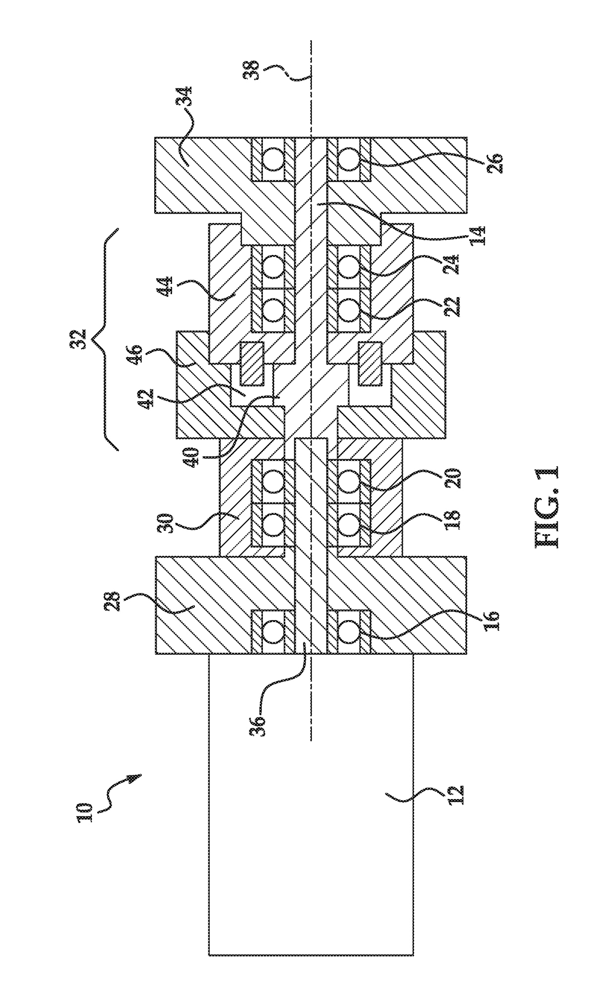
[0014]Referring now to the drawings wherein like reference numerals are used to identify identical components in the various views, FIG. 1 illustrates a power transmission assembly 10 in accordance with one embodiment of the present teachings. Assembly 10 may be provided for use in driving a propeller of a watercraft. It should be understood, however, that assembly 10 may be used to transmit power in a wide variety of applications. Assembly 10 may include an engine 12, a countershaft 14, bearings 16, 18, 20, 22, 24, 26 a clutch 28, a pulley 30, a planetary gear system 32 and an electromagnetic brake 34 in accordance with one embodiment of the present teachings.

[0015]Engine 12 generates power for use in various applications. Engine 12 may comprise any of various types of conventional internal combustion engines including both two and four stroke engines, engines having varying numbers of cylinders, and engines using various types of fluid and ignition mechanisms. Although an engine 1...


PUM


Abstract

An electromagnetic brake includes a hub disposed about a shaft and configured for rotation with the shaft about a rotational axis. An electromagnet assembly is fixed against rotation about the axis and includes a housing defining axially extending, radially spaced inner and outer poles and a brake plate extending radially therebetween. A conductor is disposed between the poles on one side of the brake plate. An armature is disposed on the other side of the brake plate and coupled to a body driven by the shaft. The electromagnet assembly, armature and hub form an electromagnetic circuit when the conductor is energized urging the armature towards the brake plate. A portion of the magnetic flux in the circuit travels radially inwardly across a first radial air gap from the inner pole to the hub and then radially outwardly across a second radial air gap from the hub to the brake plate.

Description

BACKGROUND OF THE INVENTION[0001]a. Field of the Invention[0002]This disclosure relates to an electromagnetic brake for a power transmission assembly. In particular, the disclosure relates to an electromagnetic brake having a hub that is configured to form a part of an electromagnetic circuit in the brake to reduce magnetic reluctance in the electromagnetic circuit and increase the magnetic attraction between an armature and a brake plate within the brake.[0003]b. Background Art[0004]Brakes are used to inhibit movement and are often used in power transmission assemblies to control and / or halt movement of a rotational body. In one conventional electromagnetic brake, a fixed electromagnet assembly includes a housing and a conductor disposed within the housing. A portion of the housing forms a brake plate. When current is supplied to the conductor an electromagnetic circuit is created between the housing of the electromagnet assembly and an armature that is coupled to a rotating body i...

Claims


Application Information

Patent Timeline
Patent Type & Authority Patents(United States)
IPC IPC(8): F16D63/00F16D65/14F16D27/00F16D121/20
CPCF16D63/002F16D65/14F16D2121/20F16D2027/008
Inventor BLEEKER, TODD ARLAN
Owner WARNER ELECTRIC TECH
Why Eureka
Try Eureka