Planar coil and support for actuator of fluid mover

a technology of fluid mover and actuator, which is applied in the direction of positive displacement liquid engine, dynamo-electric machines, electrical apparatus, etc., can solve the problems of increasing the overall height of the device, affecting the operation and the functional chamber of the synthetic jet device is typically quite small, so as to enhance the magnetic attraction force, enhance the magnetic force, and improve the effect of magnetic permeability separation

Active Publication Date: 2015-11-05
AAVID THERMALLOY LLV
View PDF8 Cites 4 Cited by
  • Summary
  • Abstract
  • Description
  • Claims
  • Application Information

AI Technical Summary

Benefits of technology

[0015]Some aspects of the invention provide for a coil assembly configuration that provides a physical barrier or separation between two, opposed fluidic diaphragms. The barrier or separation wall may be made of, or otherwise include, a highly magnetically permeable material which enhances a magnetic force that may be applied by current in the coil assembly on the fluidic diaphragms. This is in contrast to systems that have opposed fluidic diaphragms and a coil assembly between the diaphragms, but have only a single air gap that separates at least portions of the diaphragms from each other. However, by providing a high magnetic permeability separation wall between at least portions of the diaphragms, e.g., at a central opening of an actuator coil and / or around a periphery of the coil, magnetic attractive forces on the diaphragms may be enhanced and may be nearly equal despite the introduction of two independently oscillating air gaps in the magnetic flux circuit. For example, in one embodiment, a coil assembly may include a coil formed as an annular ring that is supported between a pair of fluidic diaphragms. In contrast to prior systems, an opening inside of the coil may be occluded or otherwise at least partially filled by a central plug or plate. The central plug may be made of a magnetically permeable material such that attractive forces on the diaphragms created by a current in the coil may be enhanced, e.g., strengthened in comparison to an arrangement in which the central plug is absent. Alternately, or in addition, a support around the periphery of the coil may be made of a magnetically permeable material, e.g., with a relative magnetic permeability of greater than one. Such an arrangement may also assist in generating nearly equal forces on the diaphragms despite the introduction of two independently oscillating air gaps in the magnetic flux circuit, which may help reduce vibration of the fluid mover housing because the diaphragms experience relatively equal, and opposite, forces that cause the diaphragms to move in the chamber with nearly equal and opposite motion, e.g., nearly the same displacement, velocity and acceleration characteristics.
[0016]In one aspect of the invention, a fluid mover includes a chamber having an outlet opening, e.g., a housing may define the chamber and may include one or more openings to the chamber through which fluid may flow. First and second fluidic diaphragms in the chamber may each have a portion that is movable in the chamber to cause fluid to move at the outlet opening. For example, the diaphragms may be caused to oscillate in the chamber in such a way as to cause fluid to move into and out of the outlet opening. A coil assembly in the chamber may be positioned between the first and second fluidic diaphragms and coupled to the fluidic diaphragms to move the movable portions of the fluidic diaphragms in the chamber. For example, a current in the coil assembly may generate a magnetic field that causes a portion of the diaphragms to move toward the coil assembly. In one embodiment, the coil assembly may include a coil with an annular shape and an opening inside the annular shape, and a center plug may at least partially occlude or fill the opening of the coil. That is, the center plug may act as a barrier or separation wall between the first and second diaphragms. In arrangements where the center plug is made of a magnetically permeable material, the center plug may enhance a strength of attractive forces on the diaphragms that is generated by current in the coil. That is, the center plug acts as part of the flux circuit loop thereby increasing actuator force by reducing total reluctance of the flux loop.
[0017]In some embodiments, a support may be arranged around the coil to support the coil in the chamber. Moreover, the support, the coil and the center plug may together define a flat structure, e.g., that includes first and second flat surfaces opposed to the first and second fluidic diaphragms, respectively. These flat surfaces may provide a reduced resistance to flow, as described above, without causing unequal forces on the diaphragms despite the introduction of two independently oscillating air gaps in the flux loop. In one embodiment, the support is formed as a flat plate with a hole in which the coil is positioned, and a first upper surface of the coil may be located in a same plane as a second upper surface of the support, and a second lower surface of the coil may be located in a same plane as a second lower surface of the support. Similarly, upper and lower surfaces of the central plug may lie in a same plane as upper and lower surfaces of the coil, e.g., the central plug may be made as a flat plate having a same thickness as the coil and the coil support. In another embodiment, the coil support is made of high permeability magnetic material such that the support acts as part of the flux circuit loop thereby increasing actuator force by reducing total reluctance.
[0018]In some embodiments, the first and second diaphragms each include first and second armatures, respectively, positioned on a side of the first and second diaphragms adjacent the coil and center plug. These armatures may each define a flat surface that is opposed to the coil and center plug. Thus, the armatures and the support / coil / center plug may define flat surfaces that are opposed to each other. Upper and lower gaps may be present between the first armature and the support, coil and center plug, and between the second armature and the support, coil, and center plug, respectively, and movement of the armatures may cause fluid to move in the upper and lower gaps, and thereby cause movement of fluid at the outlet opening. The upper and lower gaps, which may have a uniform thickness across the armatures, may be in fluid communication with each other, e.g., via holes in the coil support or center plug, which may help in maintaining a relatively equal dynamic pressure on the diaphragms.

Problems solved by technology

However, the functional chamber of a synthetic jet device is typically quite small because the entire device must be sized to fit within a space-constrained product, such as a laptop computer, and these space constraints have driven complexities in design that prevent the synthetic jet device from operating in an optimal matter.
The design complexities also result in other functional disadvantages, such as increasing an overall height of the device, introducing complexities in device manufacturing and assembly, and others.
This arrangement may not be optimal for a variety of reasons, such as providing an irregular and complex flow path for fluid in an area where the diaphragm portion is received into the coil opening, reducing an effective pumping area of the diaphragm (e.g., those portions of the diaphragm that move inside the coil opening may not be as effective in moving fluid), requiring complex armature shapes or other configurations, increasing an overall height of the diaphragm / coil structure, and others.

Method used


Image

  • Planar coil and support for actuator of fluid mover
  • Planar coil and support for actuator of fluid mover
  • Planar coil and support for actuator of fluid mover

Examples


Embodiment Construction

[0028]Aspects of the invention are not limited in application to the details of construction and the arrangement of components set forth in the following description or illustrated in the drawings. Other embodiments may be employed and aspects of the invention may be practiced or be carried out in various ways. Also, aspects of the invention may be used alone or in any suitable combination with each other. Thus, the phraseology and terminology used herein is for the purpose of description and should not be regarded as limiting.

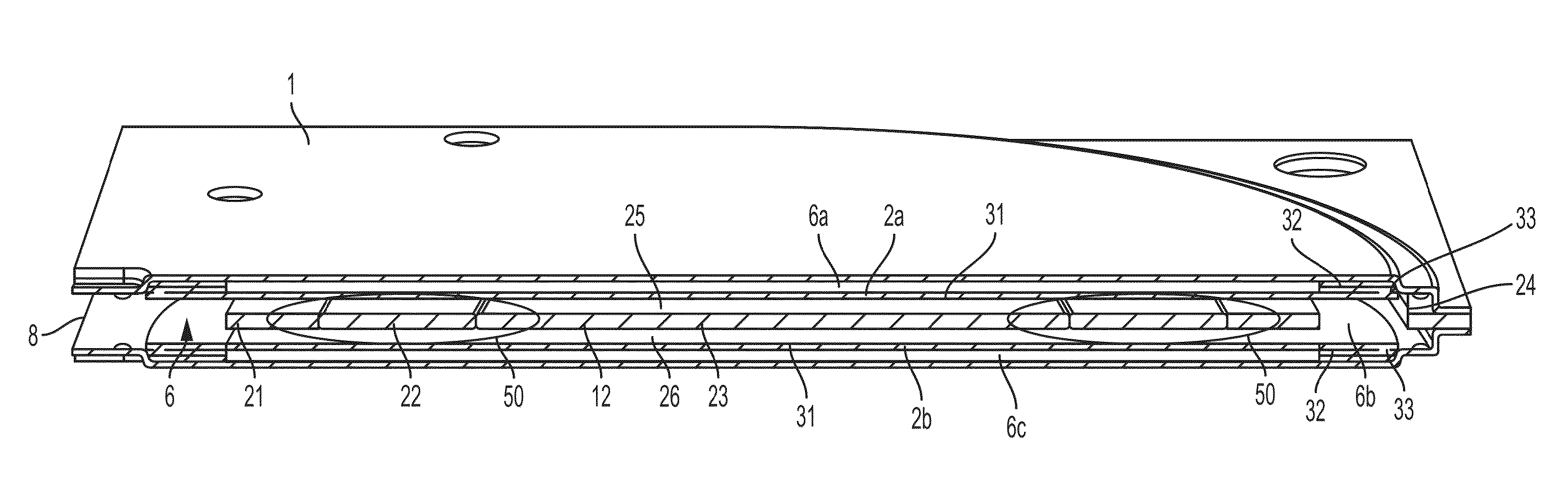
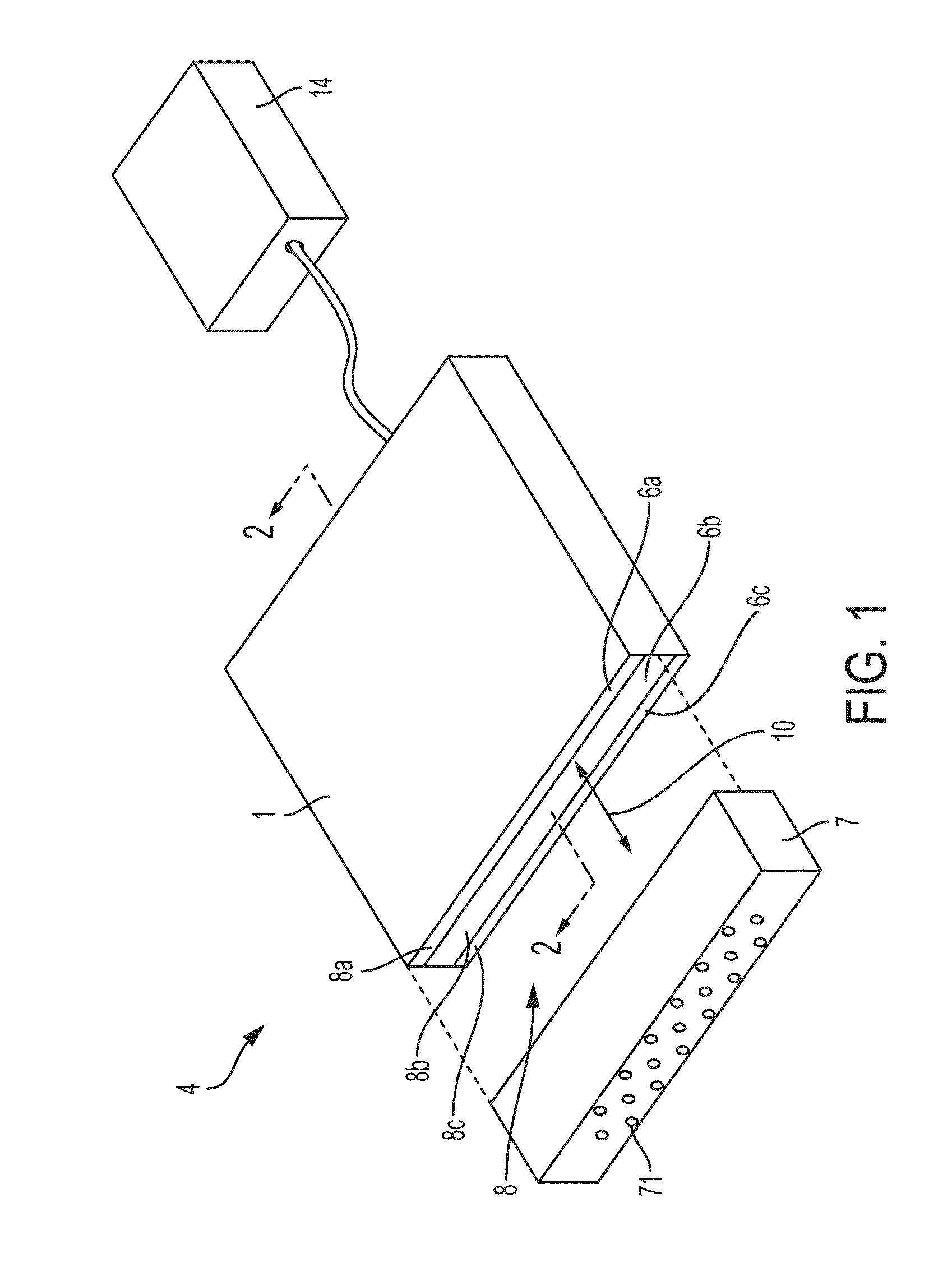
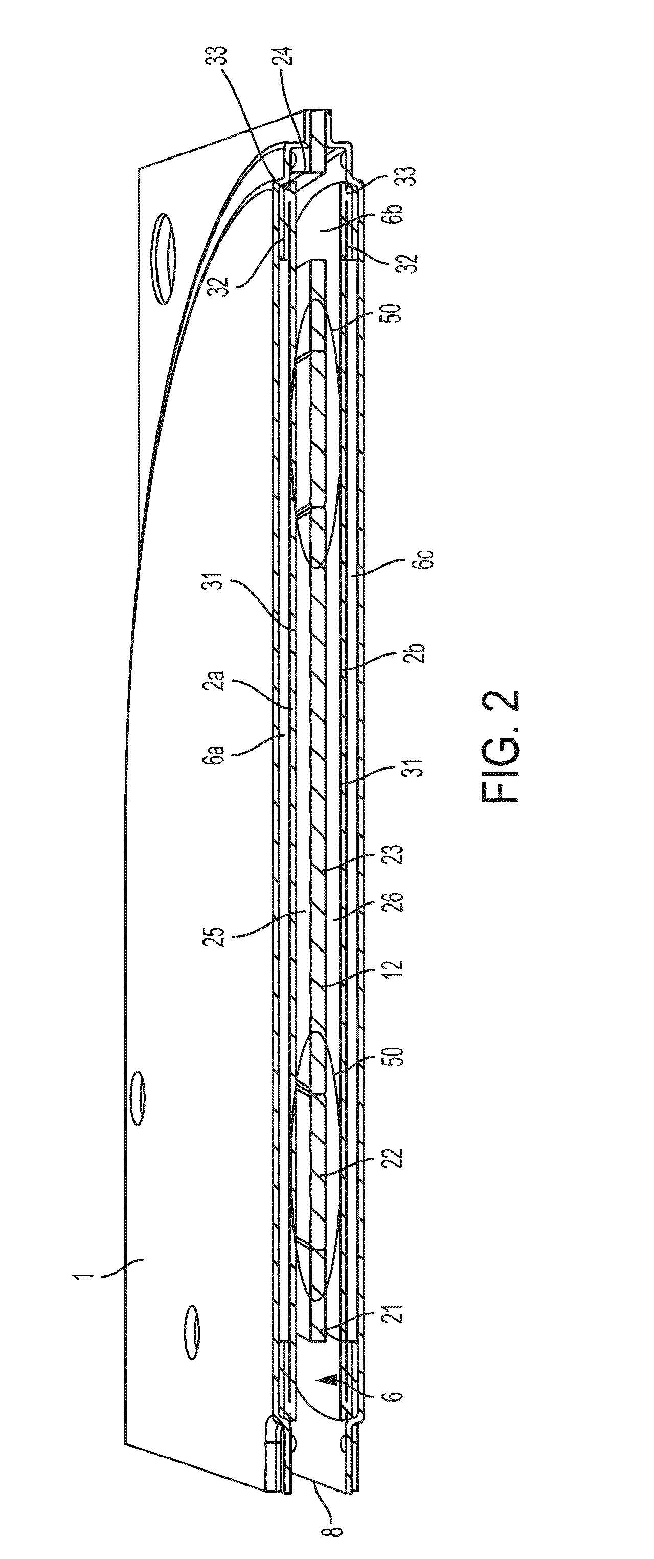
[0029]FIGS. 1 and 2 show a perspective, schematic view and a sectional view of a fluid mover 4, respectively, in an illustrative embodiment that includes a housing 1 that defines a chamber 6 having an internal volume in which first and second diaphragms 2a, 2b and a coil assembly 12 are located. In this embodiment, the internal volume of the chamber 6 is divided into three main sections: a first outer chamber 6a located above the first diaphragm 2a, a central ...


PUM


Abstract

A fluid mover includes a chamber with one or more outlet openings, first and/or second fluidic diaphragm(s) having a portion movable in the chamber to cause fluid to move at the outlet opening, and a coil assembly magnetically coupled to the fluidic diaphragm to move the movable portion of the fluidic diaphragm(s) in response to a current in the coil. The coil assembly includes a coil with an opening, and a plug may be positioned in the opening and/or a support may be positioned around a periphery of the coil. The plug and/or the support may have a magnetic permeability greater than one and be arranged so magnetic field lines created by the coil pass through the plug and/or support. The coil, plug and/or support may define a flat surface, e.g., such that a uniform gap is present between the diaphragm(s) and the coil, plug and/or support.

Description

CROSS REFERENCE TO RELATED APPLICATION[0001]This application claims the benefit of U.S. Provisional Application No. 61 / 988429, filed May 5, 2014, which is hereby incorporated by reference in its entirety.BACKGROUND OF THE INVENTION[0002]1) Field of Invention[0003]This invention relates generally to the pumping of fluids in positive displacement pumping devices, otherwise known as fluid movers, such as liquid pumps, gas compressors and synthetic jets and in general to the transfer of energy to fluids.[0004]2) Description of Related Art[0005]When compared to rotary, piston, centrifugal and other pumping approaches, diaphragms provide a lower profile means for creating a cyclic positive displacement for small fluid movers such as pumps, compressors and synthetic jets. One type of diaphragm-type fluid mover, i.e., synthetic jet devices, can provide significant energy savings when used for cooling high power density and high power dissipation electronics products such as for example serv...

Claims


Application Information

Patent Timeline
Patent Type & Authority Applications(United States)
IPC IPC(8): F04B43/04
CPCF04B43/04F04B45/043F04B45/047H02K33/16
Inventor KANG, SUKHVINDER S.LUCAS, TIMOTHY SWAIN
Owner AAVID THERMALLOY LLV
Why Eureka
Try Eureka