
Core cap for loudspeaker

a loudspeaker and core cap technology, applied in the field of loudspeakers, can solve problems such as creating unintended problems in the operation of the core cap, and achieve the effects of reducing the reluctance of the core cap 122, and reducing the ability to carry magnetic flux

Active Publication Date: 2006-08-17
HARMAN INT IND INC
View PDF3 Cites 4 Cited by
  • Summary
  • Abstract
  • Description
  • Claims
  • Application Information

AI Technical Summary

Benefits of technology

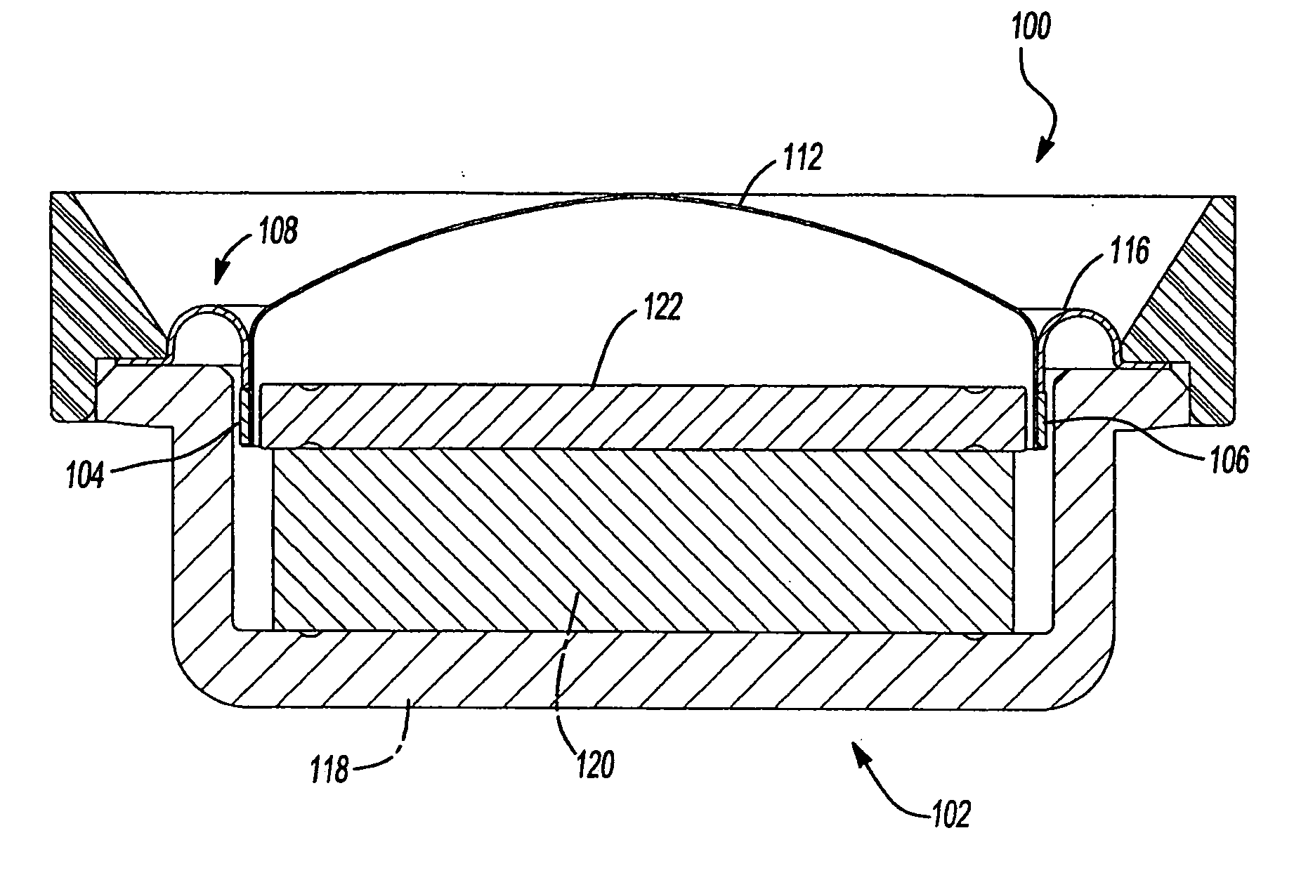
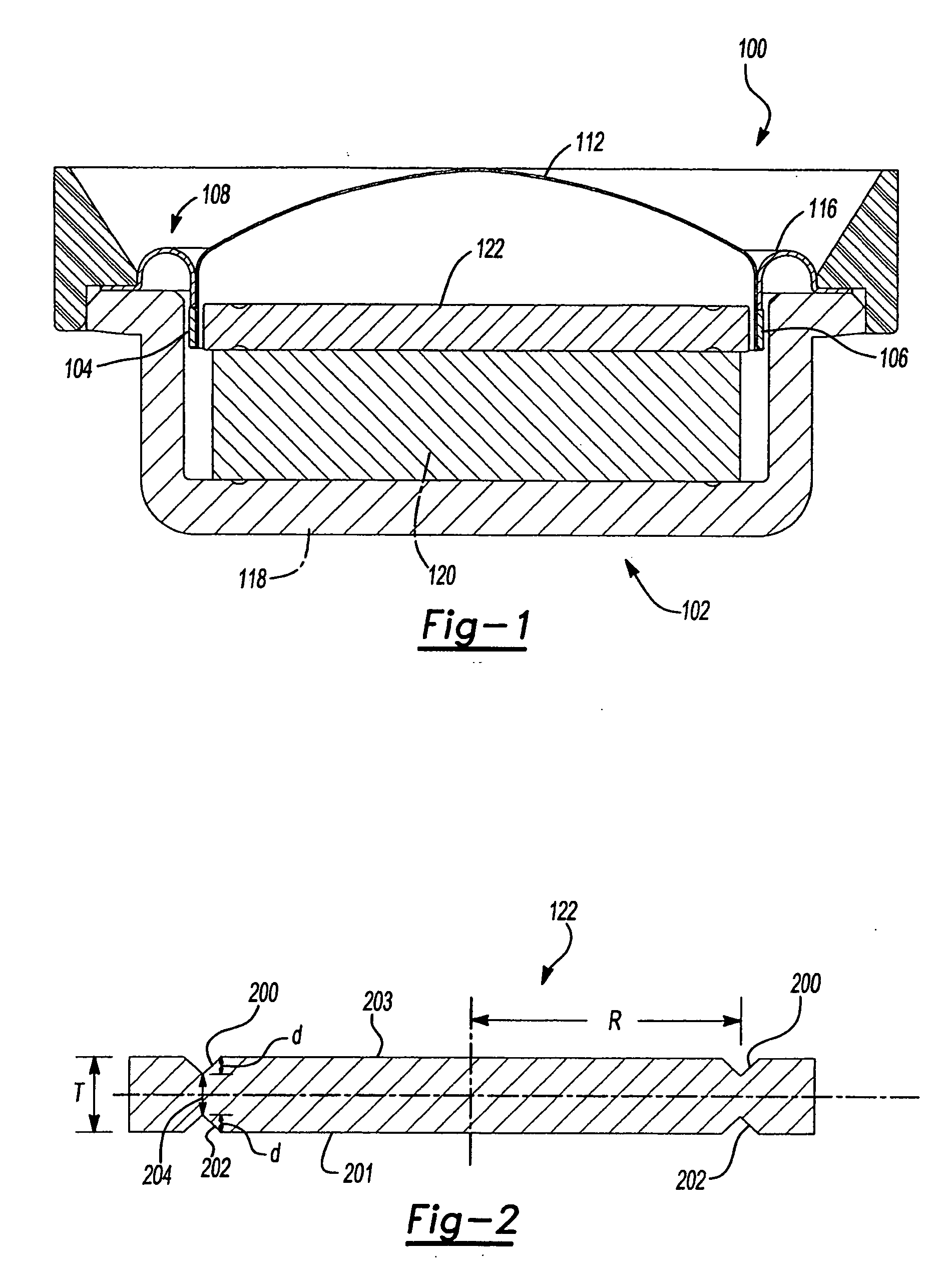
[0010] The core cap of the prior art creates the unintended consequence of reducing the ability to carry magnetic flux from the permanent magnet 120 into the working air gap 104. By narrowing the cross-section, (as shown at location 204 in FIG. 2) the reluctance of the core cap 122 is effectively increased. Consequently, the core cap's 122 ability to carry magnetic flux is reduced. Accordingly, the invention provides an improved top plate or core cap for use with loudspeakers having a shell-pot design that includes offset adhesive control grooves on the opposite faces of the disk-like core cap.
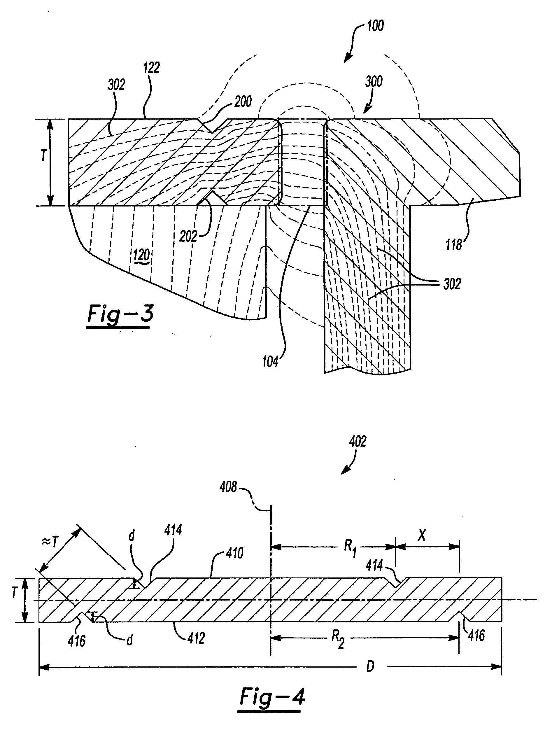
[0011] With the improved core cap design, the magnetic reluctance added by the grooves may be reduced by approximately 50 percent. This reduction in reluctance is accomplished by offsetting, along at least a portion of the grooves, the position of the grooves relative to one another. The grooves may be offset or staggered by an amount that is sufficient to increase the smallest dimension between any feature of the grooves to about the nominal thickness of the core cap. Offsetting the adhesive control grooves diminishes the cross-sectional reduction in the core cap to the equivalent of having only a single groove (i.e., a groove on only one surface of the core cap) yet maintains the assembly error-proofing of having adhesive control grooves on both surfaces of the core cap. Consequently, the core cap of this invention provides a magnetic advantage over the prior art, while maintaining the assembly advantage of core cap orientation error-proofing.

Problems solved by technology

Though convenient for manufacturing, the additional groove 200 may create unintended problems in the operation of the core cap.

Method used


Image

  • Core cap for loudspeaker
  • Core cap for loudspeaker
  • Core cap for loudspeaker

Examples


Embodiment Construction

[0021] As discussed in the background, the adhesive control grooves 200 and 202 allow for easier manufacturing since the orientation of the cap is error proof. However, the orientation of the control grooves 200 and 202 may cause unintended problems in the core cap 122. Examining the core cap shown in FIG. 2, the core cap 122 is “necked down,” having a cross-sectional dimension 204 that is smaller than the core cap's 122 nominal thickness T. This is due to the radial location of the two adhesive control grooves 200 and 202 on the opposing surfaces 201 and 203 of the core cap 122. The amount that the thickness of the core cap 122 is reduced is simply the sum of the depths d, of the opposing grooves 200 and 202 (i.e., 2d). In loudspeaker applications where the nominal thickness T of the core cap 122 is already relatively thin (e.g., in tweeters), the sum of the depths d of the opposing grooves 200 and 202 can be a significant percentage of the nominal thickness T of the core cap 122. ...


PUM


Abstract

A core cap or top plate for use with loudspeakers that includes offset adhesive control grooves on the opposite faces of the disk-like core cap is disclosed. The grooves are offset from one another by a distance that makes the smallest dimension between any feature of the grooves about the same as the nominal thickness of the core cap. The core cap increases the magnetic flux capacity over prior art core cap designs, while maintaining features advantageous to error-proof the orientation of the core cap in the loudspeaker.

Description

BACKGROUND OF THE INVENTION [0001] 1. Field of Invention [0002] The invention relates generally to a loudspeaker of the type having a magnetic circuit comprising a permanent magnet upon which is positioned a top plate or “core cap.” In particular, the invention relates to an improved core cap that increases its capacity to use the magnetic energy available from the magnet, while maintaining advantageous features for simplifying loudspeaker assembly. [0003] 2. Related Art [0004] Loudspeakers may have a shell-pot design. Such loudspeakers are commonly of physically small dimensions and are used in loudspeaker applications for reproducing sound in the mid-to-high frequency ranges, such as a tweeter, for example. In FIG. 1, a simplified cross-section of a typical loudspeaker 100 of this type is shown. [0005] The loudspeaker 100 is a diaphragm-type loudspeaker. Loudspeaker 100 includes a magnetic circuit 102 that produces a stationary magnetic field of high flux density in a narrow, work...

Claims


Application Information

Patent Timeline
IPC IPC(8): H04R11/02
CPCH04R9/025
Inventor STEERE, JOHN F.HUTT, STEVEN W.FENWICK, RONALD E.
Owner HARMAN INT IND INC
Learn More