
System and method of acquiring three-dimensional coordinates using multiple coordinate measurement devices

a technology of coordinate acquisition and measurement device, applied in the field of system and method of acquiring three-dimensional coordinates, can solve the problems of slow case, image may not properly register relative to each other,

Active Publication Date: 2017-06-20
FARO TECH INC
View PDF663 Cites 36 Cited by
  • Summary
  • Abstract
  • Description
  • Claims
  • Application Information

AI Technical Summary

Benefits of technology

The invention provides a method for determining the 3D coordinates of an object surface using a laser tracker and a portable structured light scanner. The scanner has two cameras and a light projector that produce a pattern of light on the surface. The tracker has a frame of reference and measures the position and orientation of the scanner in relation to the surface. The 3D coordinates of points on the surface are determined based on the location, orientation, and projector position. This method allows for accurate and precise 3D measurements of objects.

Problems solved by technology

TOF systems have advantages in being accurate, but in some cases may be slower than systems that project a plurality of light spots onto the surface at each instant in time.
However, if the object contains a relatively large flat or curved surface, the images may not properly register relative to each other.

Method used


Image

  • System and method of acquiring three-dimensional coordinates using multiple coordinate measurement devices
  • System and method of acquiring three-dimensional coordinates using multiple coordinate measurement devices
  • System and method of acquiring three-dimensional coordinates using multiple coordinate measurement devices

Examples


Embodiment Construction

[0019]Embodiments of the present invention provide advantages in registration of images acquired by a scanner device. Embodiments of the invention provide further advantages in the tracking of a handheld scanner device with a coordinate measurement device such as a laser tracker.

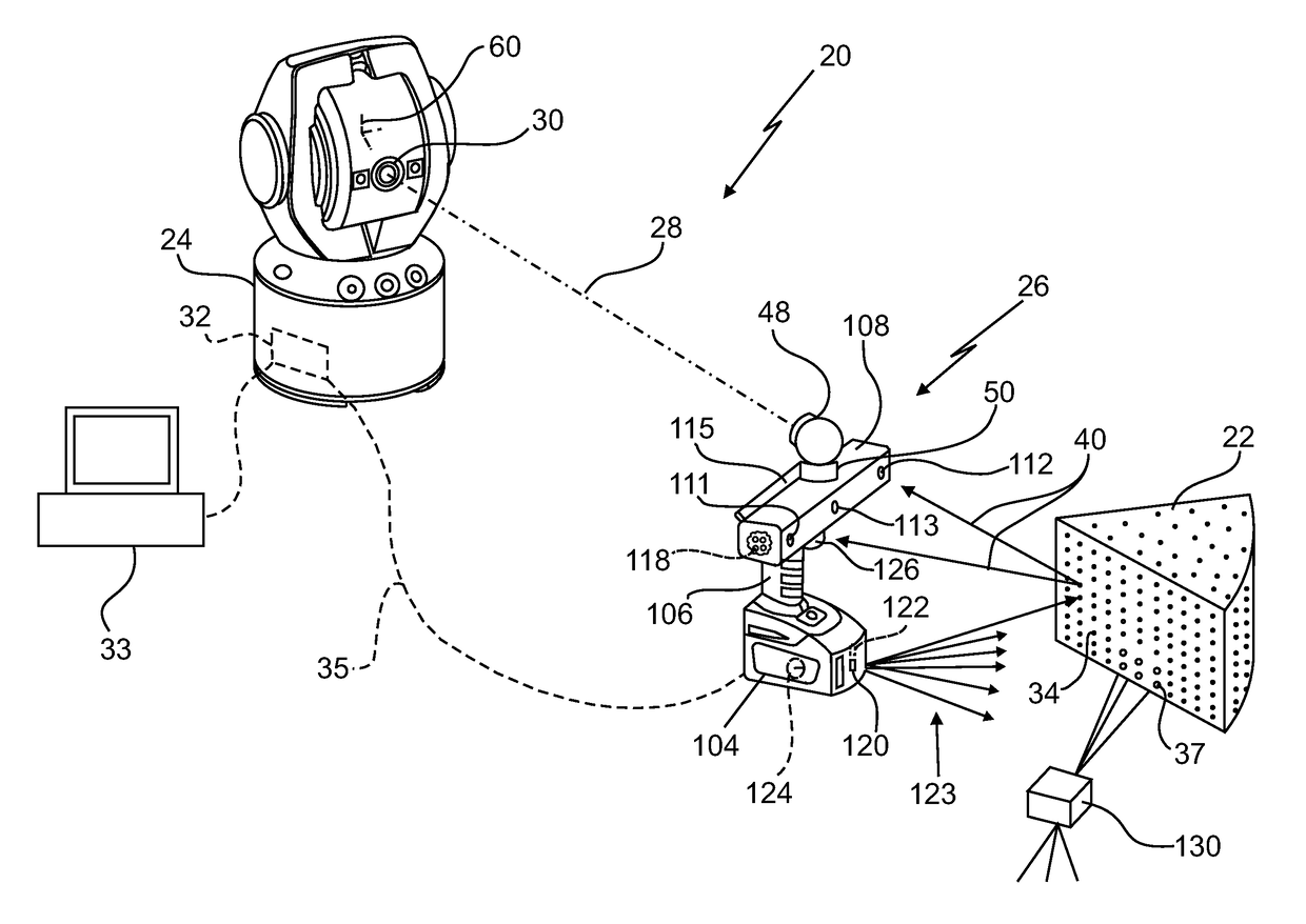
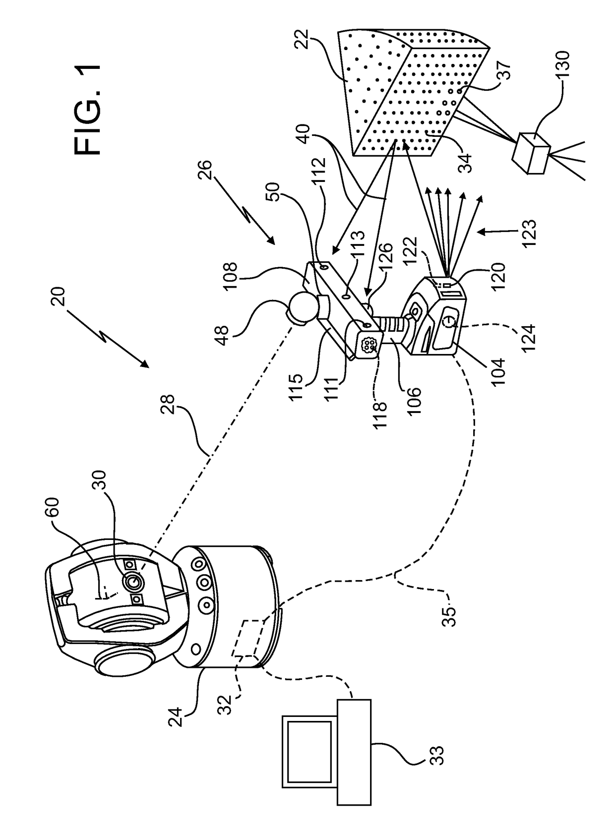
[0020]Referring to the FIG. 1, a system 20 is shown for measuring the three-dimensional coordinates of an object 22. The system includes a first coordinate measurement device, such as six degree-of-freedom (six-DOF) laser tracker 24 that cooperates with a six-DOF retroreflector. In one embodiment the six-DOF retroreflector may be a six-DOF spherically mounted retroreflector (SMR) 48, attached to a second coordinate measurement device, such as scanner 26.

[0021]The laser tracker 24 includes a light source that emits light, for example, a laser, and a distance meter. The light source and distance meter are configured to emit and receive light 28 via an aperture 30. The distance meter may be an absolute distance...


PUM


Abstract

A method is provided of determining three-dimensional coordinates of an object surface with a laser tracker and structured light scanner. The method includes providing the scanner having a body, a pair of cameras, a projector, and a processor. The projector and cameras are positioned in a non-collinear arrangement. The projector is configured to project a first pattern onto the surface. The method also includes providing the tracker which emits a beam of light onto the retroreflector. The tracker receives a reflected beam of light. The first location is measured with the tracker. The first orientation is measured with the tracker. The first surface pattern is projected onto the surface. A pair of images of the surface pattern is acquired with cameras. The processor determines the 3D coordinates of a first plurality of points in the tracker frame of reference based in part on epipolar constraints of the cameras and projector.

Description

CROSS REFERENCE TO RELATED APPLICATIONS[0001]The Present Application is a continuation-in-part application of U.S. patent application Ser. No. 13 / 443,946 filed on Apr. 11, 2012, which is a nonprovisional application of U.S. Patent Application Ser. No. 61 / 592,049 filed on Jan. 30, 2012 and U.S. patent application Ser. No. 61 / 475,703 filed on Apr. 15, 2011, all of which are incorporated herein by reference in their entirety.BACKGROUND OF THE INVENTION[0002]The subject matter disclosed herein relates to a system and method of acquiring three-dimensional coordinates of points on a surface of an object and in particular to a system and method of operating a laser tracker in conjunction with a scanner device to track the position and orientation of the scanner device during operation.[0003]The acquisition of three-dimensional coordinates of an object or an environment is known. Various techniques may be used, such as time-of-flight (TOF) or triangulation methods for example. A TOF system ...

Claims


Application Information

Patent Timeline
Patent Type & Authority Patents(United States)
IPC IPC(8): H04N13/02G01S7/48G01S7/481G01B11/245G01B11/25G01S17/89G01S17/66G01S17/42G01C15/00G01S7/491
CPCH04N13/0253G01B11/245G01B11/2513G01B11/2518G01B11/2545G01C15/002G01S7/4808G01S7/4813G01S7/4818G01S7/491G01S17/42G01S17/66G01S17/89H04N13/246H04N13/204H04N13/25H04N13/254
Inventor TOHME, YAZID
Owner FARO TECH INC
Learn More