Electronic pipe

a technology of electronic pipes and pipes, applied in the field of electronic pipes, can solve the problems of affecting the health of smokers, unable to achieve the effective peak concentration of nicotine in the blood of smokers, and remains extremely difficult for smokers to quit smoking

Active Publication Date: 2017-06-27
HEALTHIER CHOICES MANAGEMENT CORP
View PDF7 Cites 48 Cited by
  • Summary
  • Abstract
  • Description
  • Claims
  • Application Information

AI Technical Summary

Problems solved by technology

Although smoking may cause serious respiratory diseases and cancer, it remains extremely difficult for smokers to quit smoking.
It has been proven that passive smoking can be more harmful to non-smokers than smoking is to the smoker.
Although these cigarette and pipe substitutes are free from tar, their major disadvantage is that an effective peak concentration of nicotine cannot be reached in the blood of a smoker due to slow absorption of the nicotine.
In addition, these cigarette and pipe substitutes cannot satisfy the habitual smoking actions of a smoker, for example, the inhaling action and the physical manipulation of the cigarette or pipe itself.

Method used


Image

  • Electronic pipe
  • Electronic pipe
  • Electronic pipe

Examples


first embodiment

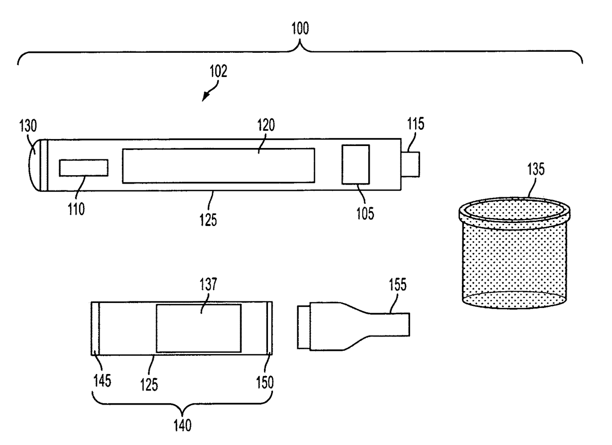
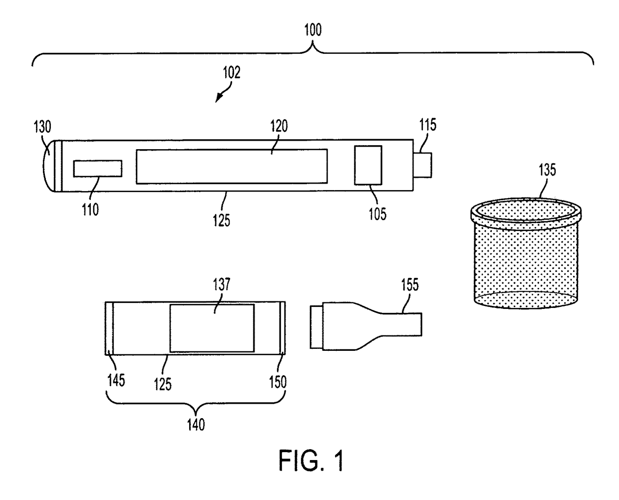
[0021]the electronic pipe 100 illustrated in FIG. 1 includes several features. For example, the battery 120 is rechargeable and can be plugged into a USB or wall adaptor for charging. Also, the printed circuit board 105 includes a locking capability. When the pressable button (not shown) is pressed 3 times within 2 seconds, the rechargeable battery 120 is locked (i.e., power is unavailable to any component of the electronic pipe 100). When the pressable button (not shown) is pressed 3 times within 2 seconds, again, the rechargeable battery 120 is unlocked. This safety feature ensures that the electronic pipe 100 will not begin heating the heating net 135 when the electronic pipe 100 is located in a user's pocket or when not in use.

[0022]In addition, the printed circuit board 105 has a counting function which counts how many times a user presses the pressable button, and the count is displayed on the LCD display 110. This function is reset when the rechargeable battery 120 is recharg...

second embodiment

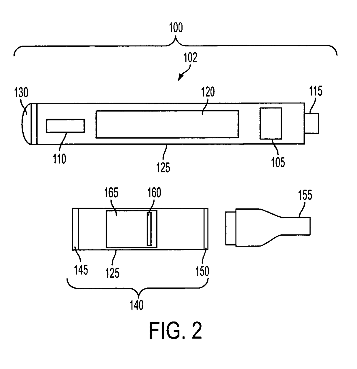
[0025]Referring now to FIG. 2, a second embodiment electronic pipe 100 is illustrated. The elements and reference numbers discussed above in connection with the embodiment illustrated in FIG. 1 apply to the embodiment illustrated in FIG. 2. Similar to the embodiment illustrated in FIG. 1, a first pipe section 102 includes a printed circuit board, or an integrated circuit, or a memory module encoded with a program (with the integrated circuit or the memory module possibly mounted on a printed circuit board) 105 located within the first pipe section 102. The printed circuit board 105 communicates with a liquid crystal display (LCD) 110 located on the first pipe section 102 so that the LCD is visible to a user. The LCD display 110 communicates with the printed circuit board 105 and a charging head 115 in the form of a male USB jack or outlet that enables the rechargeable battery 120 to be charged. In one embodiment, the rechargeable battery 120 is located within the first pipe section ...

third embodiment

[0036]Referring now to FIG. 3, a third embodiment electronic pipe 100 is illustrated. The features, elements and reference numbers discussed above in connection with FIGS. 1 and 2 apply to the embodiment illustrated in FIG. 3. As shown in FIG. 3, the combustible material reservoir 165 is located within the second pipe section 140. That is, in one embodiment, the second pipe section 140 has a circular cross-section, with an aperture, or opening at the mouthpiece receiver 150 sized to receive both the mouthpiece 155 and a combustible material that is placed into the second pipe section 140 before the mouthpiece 155 is placed over the mouthpiece receiver 150. In this embodiment, only a small hole, or aperture (not shown) is located in the second pipe section 140 so that air can be provided to the combustible material reservoir 165, which is positioned entirely within the second pipe section 140.

[0037]One feature of this embodiment is that the combustible material cannot “spill” from an...


PUM


Abstract

An electronic pipe is provided. The electronic pipe includes a first pipe section having an electronic module and a first connector element that communicates with the electronic module. A second pipe section is structured to be removeably attachable to the first pipe section, the second pipe section including a combustible material reservoir having a passageway that communicates with a mouthpiece receiver, with an aperture located on a surface of the second pipe section, the aperture communicating with the combustible material reservoir so that a fluid exterior to the electronic pipe can pass into the aperture, through the combustible material reservoir and into the passageway that communicates with the mouthpiece receiver and a second connector element structured to removeably couple to the first connector element, with both connector elements structured to transmit an electric current from the battery to a heating element located within the combustible material reservoir.

Description

[0001]Priority is claimed to U.S. provisional patent application Ser. No. 61 / 743,720, filed Sep. 10, 2012, entitled: “Electronic Pipe,” which is referred to and incorporated herein in its entirety by this reference.FIELD OF THE INVENTION[0002]The present invention relates to an electronic pipe, in particular to an electronic pipe that includes removable components.BACKGROUND OF THE INVENTION[0003]Despite the fact that “smoking is harmful to your health”, the number of smokers worldwide is up to 1 billion, and the number is increasing every year. In 2003, the World Health Organization (WHO) concluded a global Framework Convention on Tobacco Control. According to the statistical data from WHO, about 4.9 million people die of diseases caused by smoking each year. Although smoking may cause serious respiratory diseases and cancer, it remains extremely difficult for smokers to quit smoking.[0004]The active ingredient in a cigarette or pipe is nicotine. During smoking, nicotine, along wit...

Claims


Application Information

Patent Timeline
Patent Type & Authority Patents(United States)
IPC IPC(8): A24F47/00A24F1/00A24F40/10A24F40/40A24F40/50
CPCA24F1/00A24F47/008A24F40/40A24F40/10A24F40/50A24F40/20
Inventor CYPHERT, GILBERTHUANG, XUANDONGBALDER, EDWIN
Owner HEALTHIER CHOICES MANAGEMENT CORP
Why Eureka
Try Eureka