Roller for a pendulum mass of a centrifugal force pendulum

a centrifugal force, pendulum technology, applied in the direction of friction clutches, mechanical devices, flywheels, etc., to achieve the effect of smoothing out the resulting vibration and good vibration isolation properties

Active Publication Date: 2017-06-27
SCHAEFFLER TECH AG & CO KG
View PDF17 Cites 4 Cited by
  • Summary
  • Abstract
  • Description
  • Claims
  • Application Information

AI Technical Summary

Benefits of technology

[0008]This one-piece configuration makes it possible to manufacture the roller particularly simply and economically. The roller may also be mounted very easily as a result of an insertion opening in the pendulum mass and / or flywheel. In another variant of the centrifugal pendulum, at least one of the retaining sections is put in place only after the assembly. Thereby an insertion opening may be dispensed with.
[0035]Nowadays, most motor vehicles have front-wheel drive and therefore place the drive unit, such as an internal combustion engine or an electric motor, for example, forward of the driver's compartment and transverse to the principal direction of travel. With such an arrangement, the space requirement is particularly low and it is therefore particularly advantageous to use a small clutch.

Problems solved by technology

A system of this type has disadvantages in particular for friction clutches for small vehicles, because in small vehicles the components must have particularly small dimensions.

Method used


Image

  • Roller for a pendulum mass of a centrifugal force pendulum
  • Roller for a pendulum mass of a centrifugal force pendulum
  • Roller for a pendulum mass of a centrifugal force pendulum

Examples


Embodiment Construction

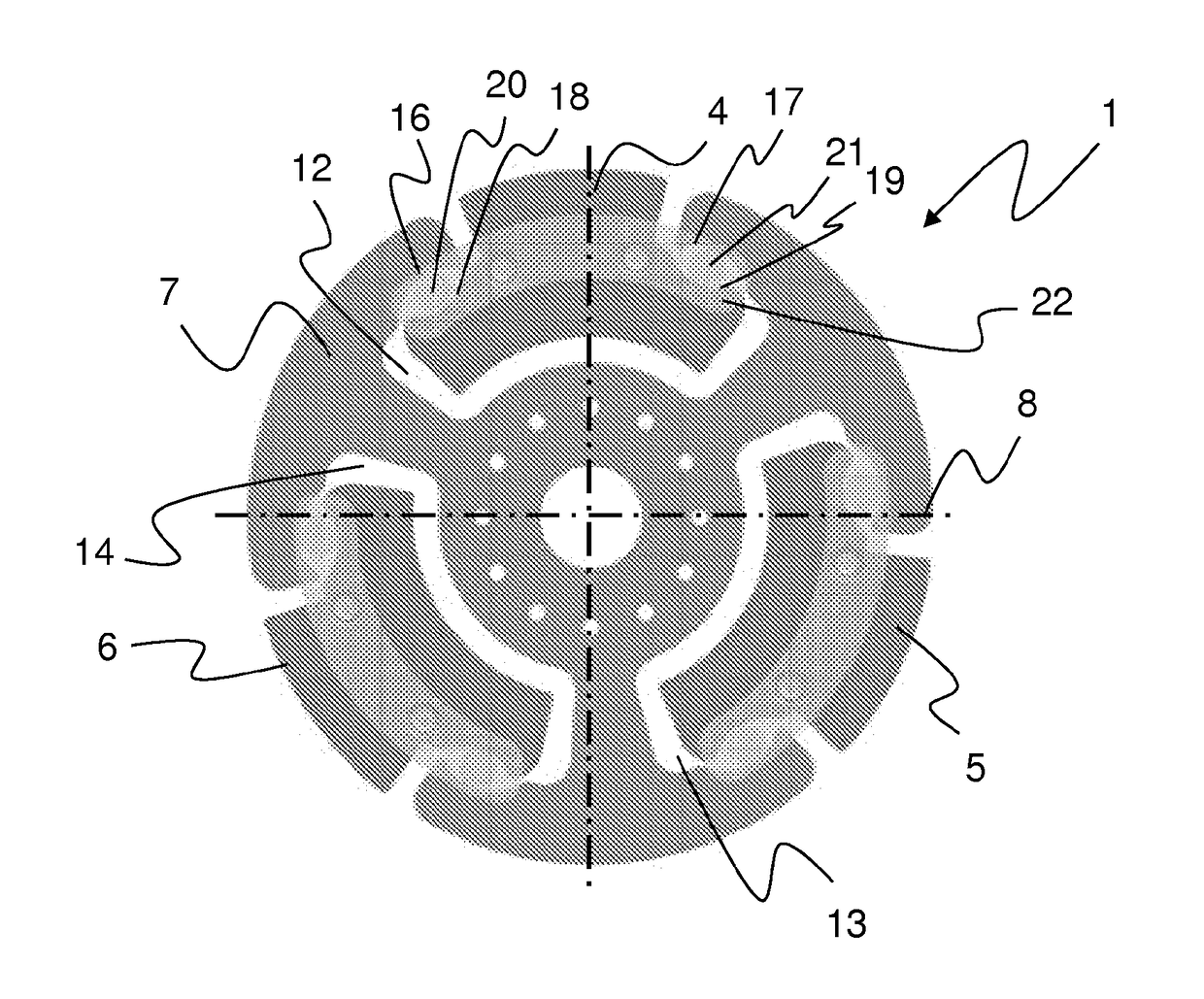
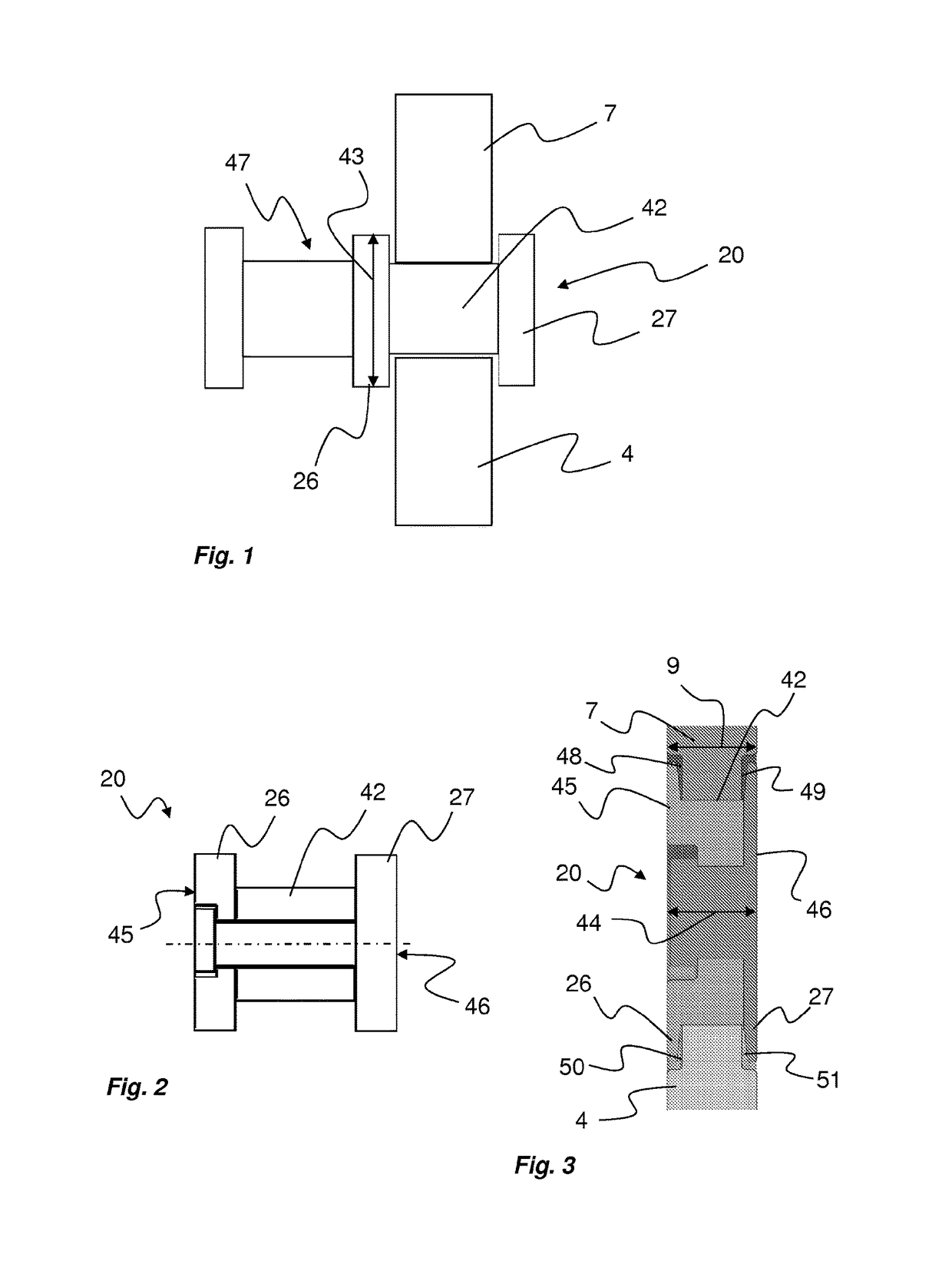
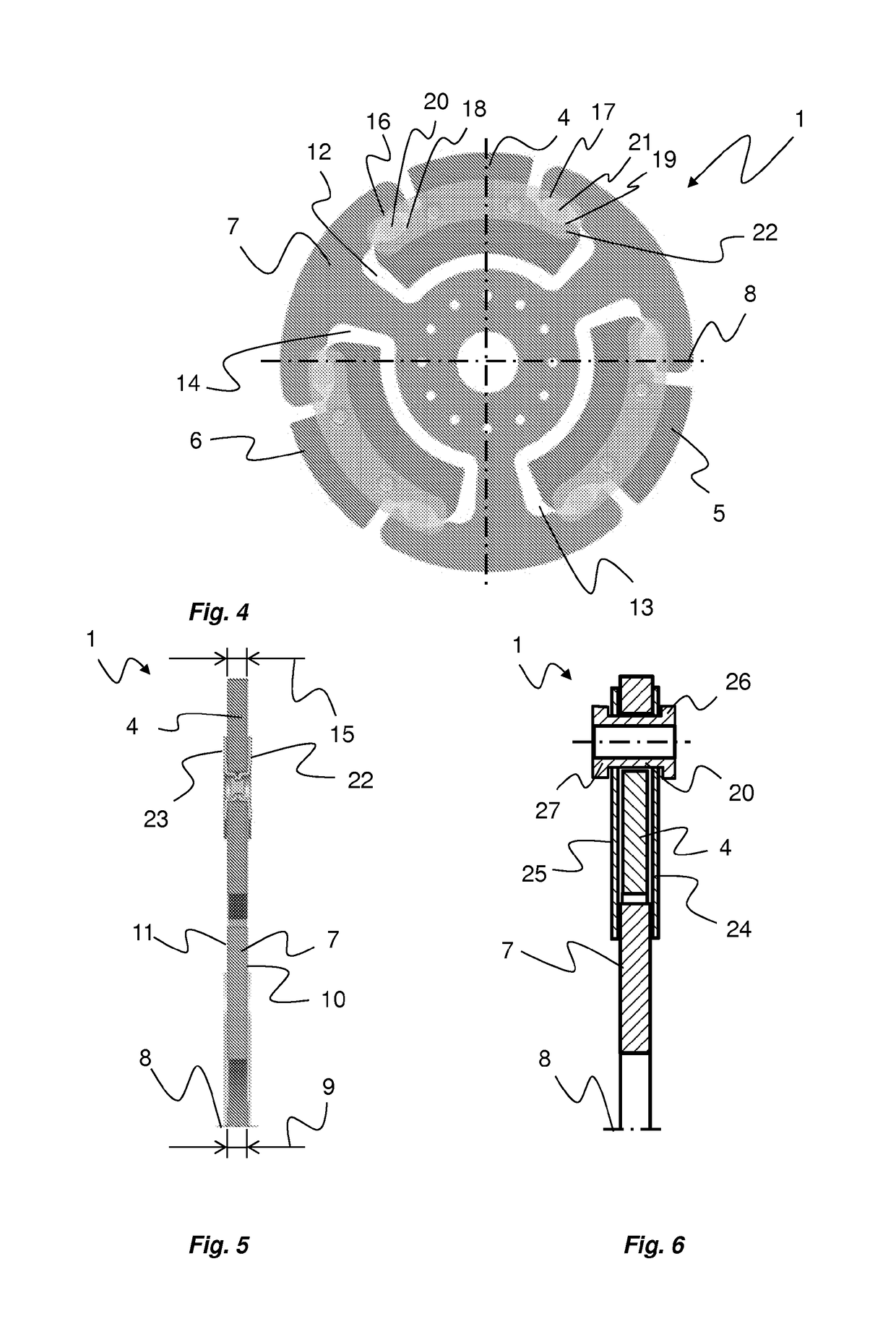
[0048]FIG. 1 shows a one-piece roller 20 which is situated between a flywheel 7 and a pendulum mass 4. Rolling section 42 makes an absorption movement of the pendulum mass 4 possible. Pendulum mass 4 is axially secured on flywheel 7 with the aid of first retaining section 26 and second retaining section 27. Diameter 43 of retaining sections 26, 27 is enlarged with respect to rolling section 42. In this case, roller 20 is connected to an additional roller 47.

[0049]FIG. 2 shows a two-piece roller 20, first retaining section 26 being formed in one piece with first part 45 and second retaining section 27 and rolling section 42 being formed in one piece with second part 46. In this case roller 20 has a form-fitted joint by way of a rivet, for example.

[0050]FIG. 3 shows an additional two-piece roller 20 which is situated between a flywheel 7 and a pendulum mass 4. The rest of the configuration is similar to the configuration illustrated in FIG. 2. In this case, a first bevel 48 and a seco...


PUM


Abstract

A roller (20) for a pendulum mass (4, 5, 6) of a centrifugal force pendulum (1), including a rolling section (42), a first maintaining section (26) and a second maintaining section (27). The maintaining sections have a larger diameter than the rolling section, and the roller (20) has a width (44) which is smaller or the same size as the first depth (9) of the centrifugal force pendulum. Due to roller (20), a centrifugal force pendulum can be constructed for particularly flat couplings. In particular, the total weight of the friction clutch is reduced and the mounting is simplified.

Description

[0001]The present invention relates to a roller for a pendulum mass of a centrifugal pendulum for a motor vehicle, preferably with an internal combustion engine, as well as a friction clutch and a motor vehicle with a centrifugal pendulum. In friction clutches, a centrifugal pendulum is used to suppress the transmission of undesirable vibrations, which generally originate from the internal combustion engine, to the driven system in predetermined frequency ranges.BACKGROUND[0002]In the prior art, a centrifugal pendulum is provided in the form of a flywheel and a plurality of pendulum masses, the pendulum masses being movably suspended in such a way that they absorb the vibrations that occur in a special resonance range. For this purpose, a flywheel has previously been used to which the plurality of pendulum masses were attached laterally, e.g., with the aid of rivets. On conventional friction clutches for motor vehicles, the individual pendulum masses are approximately 3 mm deep, as ...

Claims


Application Information

Patent Timeline
Patent Type & Authority Patents(United States)
IPC IPC(8): F16F15/14F16D21/06F16F15/31F16D13/70
CPCF16F15/145F16D13/70F16F15/31F16D2013/703F16D2021/0615Y10T74/2128Y10T74/2132
Inventor KUEHNLE, MICHAELWAHL, PETERMAIENSCHEIN, STEPHAN
Owner SCHAEFFLER TECH AG & CO KG
Why Eureka
Try Eureka