
Machine tool and machining control device thereof

a control device and machining technology, applied in the direction of program control, electric programme control, instruments, etc., can solve the problems of easy chatter vibration during the cutting process, drawback, and relatively weak tool stiffness, and achieve the effect of reducing chatter vibrations and facilitating and stably inhibiting them

Active Publication Date: 2017-06-27
KOMATSU LTD
View PDF18 Cites 2 Cited by
  • Summary
  • Abstract
  • Description
  • Claims
  • Application Information

AI Technical Summary

Benefits of technology

[0016]It is an object of the present invention to easily and stably inhibit chatter vibrations having occurred during a cutting process in a machine tool configured to execute cutting under a condition set based on a stability limit curve.
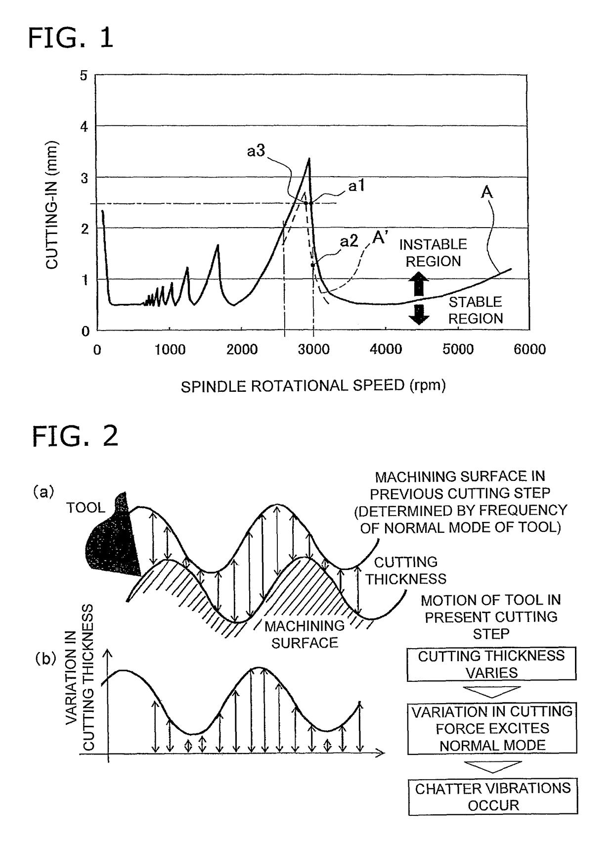
[0020]As described above, according to this aspect of the present invention, it is possible to easily shift a machining condition plotted within the instable region to the stable region by changing the spindle rotational speed. At this time, it is not required to remarkably change the spindle rotational speed. Therefore, remarkable deterioration in machining efficiency can be avoided. Further, the processing of controlling the spindle rotational speed does not require changing of a machining program, and therefore, can be executed during machining. Thus, the processing can quickly deal with machining situations on a case-by-case basis.
[0028]In view of this, in the fourth aspect of the present invention, the machining starting condition is configured to be set on the lower spindle rotational speed side within the stable region in order to easily control the spindle rotational speed and stably inhibit chatter vibrations.
[0030]When the actual stability limit curve is displaced to the lower spindle rotational speed side where the machining starting condition is set to be a relatively low spindle rotational speed within the stable region, chatter vibrations do not occur even without changing the machining starting condition. Therefore, it can be considered to reduce a machining time by increasing the spindle rotational speed.
[0036]When the actual stability limit curve is displaced to the higher rotational speed side where the machining starting condition is set to be the maximum spindle rotational speed within the stable region, chatter vibrations do not occur even without changing the machining starting condition. Therefore, it can be considered to reduce the machining time by further increasing the spindle rotational speed.
[0041]In the aspects of the present invention as described above, it is possible to easily and stably inhibit chatter vibrations that occurred during machining in a machine tool configured to execute machining under a condition set based on a stability limit curve.

Problems solved by technology

In such a tool, a distance becomes long between a blade part and a part chucked by a spindle, and thereby, the stiffness of the tool becomes relatively weak.
In such a cutting process, where the stiffness of the tool is weak as described above, variation in cutting force excites normal mode of the tool, and thereby, chatter vibrations come to easily occur during the cutting process.
It is theoretically possible to determine the cutting-in amount whereby chatter vibrations are inhibited, but a drawback is produced as follows.
At this time, the stiffness of a tool deviates from its reference stiffness and the blank dimension of a workpiece has an error or mismatch from its reference dimension.
Especially, the blank dimension of a workpiece such as a casting product or a forging product has a large error from its reference dimension.
However, when the cutting-in amount is thus remarkably reduced, a machining operation cannot be efficiently executed.
Thus, change of the cutting-in amount leads to change of the machining program, and in some cases, this cannot be handled during a machining operation.
However, it is herein assumed that the stability limit curve is displaced to be a curve A′ due to deviation in stiffness of a tool from its reference stiffness and / or an error in blank dimension of a workpiece from its reference dimension.
In such a state, it becomes difficult to stably inhibit chatter vibrations by controlling the spindle rotational speed.
Further, even when the spindle rotational speed is increased, remarkable reduction in machining time cannot be expected.

Method used


Image

  • Machine tool and machining control device thereof
  • Machine tool and machining control device thereof
  • Machine tool and machining control device thereof

Examples


Embodiment Construction

Basic Principle of Present Invention

[0054]First, a stability limit curve will be explained.

[0055]Chatter vibrations are attributed to variation in cutting thickness during a cutting process. FIG. 2 represents the situation. As represented in FIG. 2(a), when an undulation is left uncut on a workpiece in the previous cutting step, a tool in a cutting motion is configured to be slightly shifted and cut the workpiece along a target profile in the next cutting step. Therefore, as represented in FIG. 2(b), the cutting thickness varies; this results in vibratory force that is a cause of chatter vibrations; normal mode is thereby excited; thus, chatter vibrations are supposed to occur.

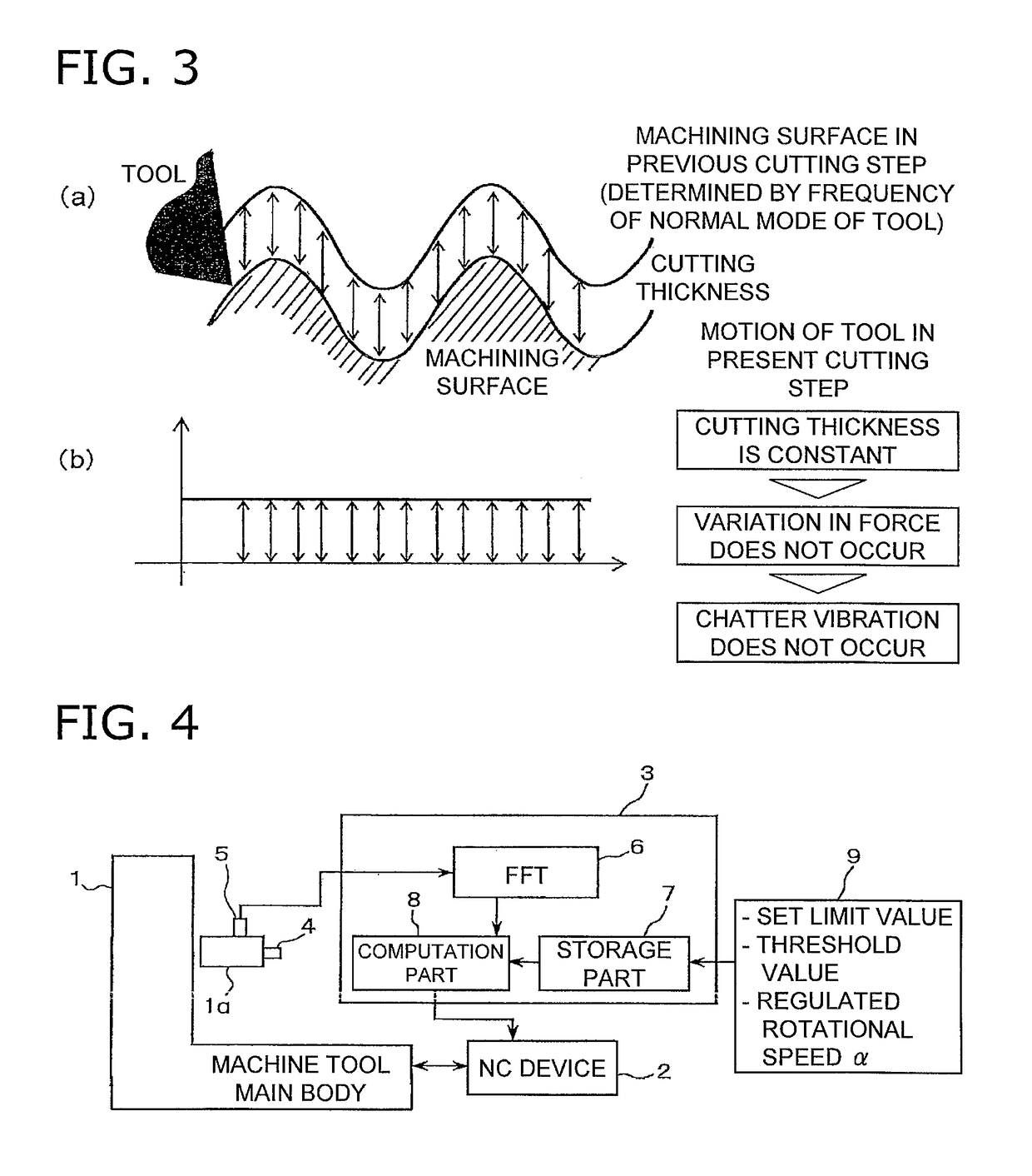
[0056]In view of this, as represented in FIG. 3, chatter vibrations can be inhibited by controlling the spindle rotational speed in accordance with the frequency of the normal mode of a tool so that the cutting thickness is kept constant. In other words, it would be possible to inhibit chatter vibrations by es...


PUM


Abstract

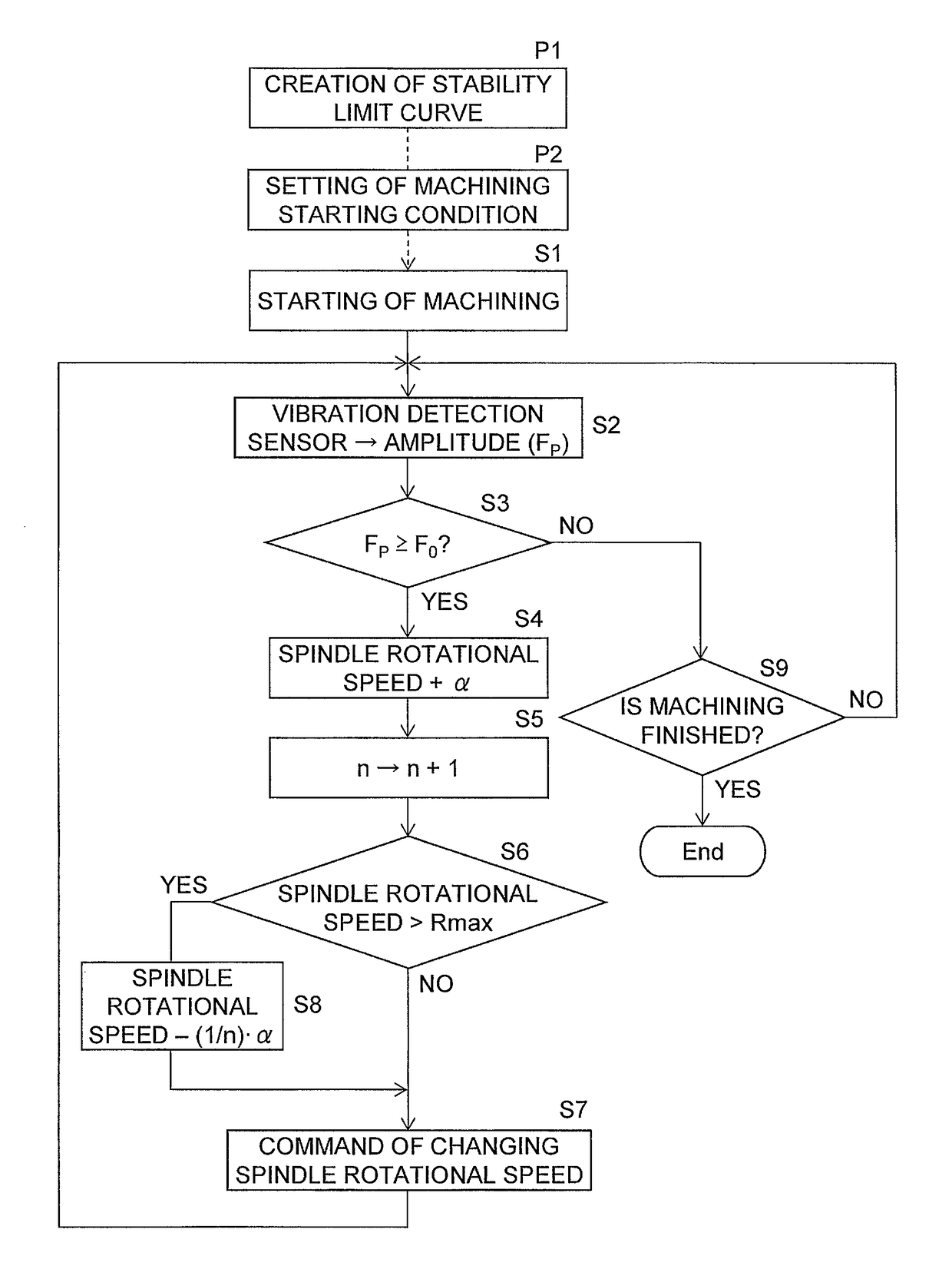
A machining control device controls spindle rotational speed. A set of stability limit curve data is stored indicating a relation between a spindle rotational speed and a limit cutting-in amount whereby chatter vibrations are inhibited. Spindle rotational speed and tool cutting-in amount in starting machining are set based on the data. Vibrations of the spindle are detected during cutting. Whether chatter vibrations have occurred is determined based on vibrations detection. Spindle rotational speed is controlled with reference to the data to inhibit chatter vibrations. Cutting-in amount in starting machining is set to be less than a maximum cutting-in amount within a stable region of the data, and spindle rotational speed in starting machining is set to be less than a rotational speed when the cutting-in amount is maximum within the stable region. Spindle rotational speed is increased by an amount of a predetermined rotational speed when chatter vibrations have occurred.

Description

CROSS-REFERENCE TO RELATED APPLICATIONS[0001]This application claims priority to Japanese Patent Application No. 2011-080696 filed on Mar. 31, 2011, and is a U.S. National stage application of International Application No. PCT / JP2012 / 057586, filed Mar. 23, 2012.BACKGROUND[0002]Field of the Invention[0003]The present invention relates to a machining control device, and particularly to a machining control device configured to control the rotational speed of a spindle to which a tool for cutting a workpiece is attached and a machine tool provided with the same.[0004]Background Information[0005]For example, in boring a workpiece with a milling tool, the tool is required to have a long length for avoiding spatial interference between the tool and the workpiece. In such a tool, a distance becomes long between a blade part and a part chucked by a spindle, and thereby, the stiffness of the tool becomes relatively weak.[0006]Now, when an undulation is left uncut on a workpiece in the previou...

Claims


Application Information

Patent Timeline
Patent Type & Authority Patents(United States)
IPC IPC(8): G05B19/18G05B19/40G05B19/404
CPCG05B19/18G05B19/404G05B2219/41115
Inventor KATAOKA, TAKAYUKINABATA, EIJIKOJIMA, NORIAKI
Owner KOMATSU LTD
Learn More