Assembly and method of plural conductive slots sharing an overheating destructive fixing element

a technology of overheating destructive fixing element and conductive slot, which is applied in the direction of electrical equipment, connection, coupling device connection, etc., can solve the problems of plastic metal overheating destructive fixing element, and achieve the effect of more safe use of slots

Active Publication Date: 2017-07-04
GREEN IDEA TECH INC
View PDF16 Cites 47 Cited by
  • Summary
  • Abstract
  • Description
  • Claims
  • Application Information

AI Technical Summary

Benefits of technology

[0013]Accordingly, in order to enable plural conductive slots to share an overheating destructive fixing element and to use the slots more safely, an assembly of plural conductive slots sharing an overheating destructive fixing element is disclosed, including a first conductive element and a second conductive element. The first conductive element is provided with a front end, a rear end, plural conductive slots, a connection portion and a contact portion. The abovementioned conductive slots are all disposed between the front end and the rear end, wherein the conductive slot closest to the front end is defined as the front end conductive slot, the conductive slot closest to the rear end is defined as the rear end conductive slot, a control section is defined between

Problems solved by technology

Furthermore, the overheating destructive fixing element is made of plastic.
Furthermore

Method used


Image

  • Assembly and method of plural conductive slots sharing an overheating destructive fixing element
  • Assembly and method of plural conductive slots sharing an overheating destructive fixing element
  • Assembly and method of plural conductive slots sharing an overheating destructive fixing element

Examples


first embodiment

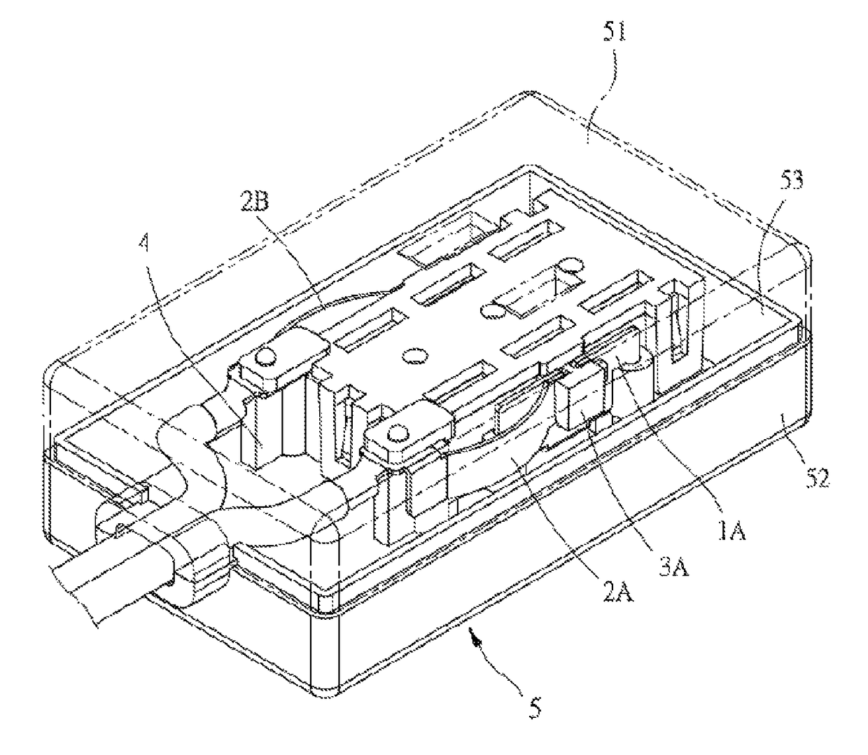
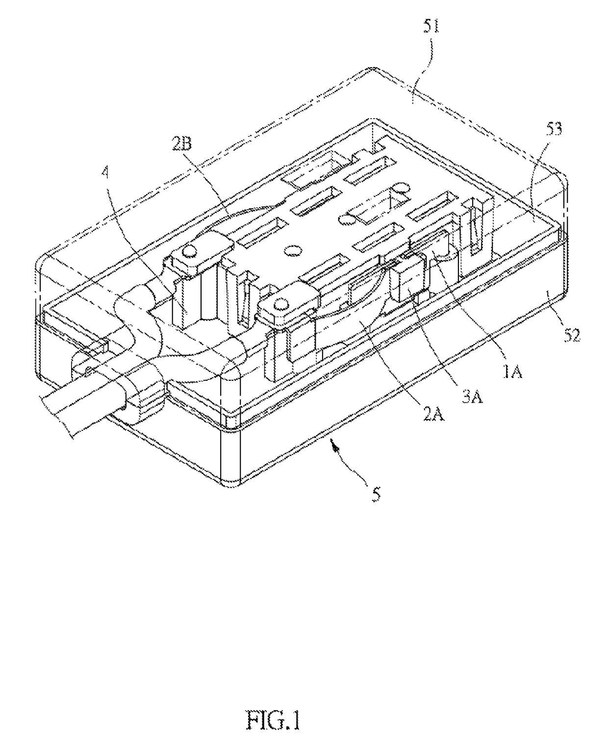
[0057]First, referring to FIG. 1 and FIG. 2 for an assembly of plural conductive slots sharing an overheating destructive fixing element, according to the present invention, the assembly in the present embodiment is, but not limited to, an extension cord; for example, the assembly can be an adaptive socket or an expansion socket. The assembly comprises two first conductive elements 1A, 1B, two second conductive elements 2A, 2B, two overheating destructive fixing elements 3A, 3B, a fixing seat 4 and a housing 5. As in the present embodiment, the abovementioned two first conductive elements 1A, 1B, two second conductive elements 2A, 2B and two overheating destructive fixing elements 3A, 3B are all in a pair respectively, and further descriptions will be only based upon the first conductive element 1A, the second conductive element 2A and the overheating destructive fixing element 3A. However, this does not mean that the abovementioned two first conductive elements 1A, 1B, the abovemen...

second embodiment

[0069]Referring to FIG. 10A and FIG. 10B, it discloses that the present invention further includes a housing 50A to accommodate and fix the first conductive elements 10A, 10B, the second conductive elements 20A, 20B, the overheating destructive fixing elements 30A, 30B and the fixing seat 40A. In addition, the housing 50A is provided with plural insertion holes 511A, with the locations of the insertion holes 511A corresponding to the locations where the conductive slots 13A (i.e., the front end conductive slot 131A and the rear end conductive slot 132A) of the first conductive elements 10A, 10B are disposed. The first conductive elements 10A, 10B are connected respectively with two electric wires A0 (i.e., a live wire and a neutral line), forming an extension cord socket. Specifically, the fixing seat 40A includes a seat unit 41A and a cover unit 42A. The seat unit 41A provides for installing the first conductive elements 10A, 10B and the second conductive elements 20A, 20B, and the...


PUM


Abstract

An assembly and method of plural conductive slots sharing an overheating destructive fixing element is disclosed, including a first conductive element, a second conductive element and an overheating destructive fixing element. The first conductive element includes a front end, a rear end, plural conductive slots, a connection portion and a contact portion. The conductive slots include a front end conductive slot and a rear end conductive slot, between which a control section is defined. The connection portion is disposed on the control section, and the contact portion connects the connection portion. The second conductive element contacts the contact portion by the overheating destructive fixing element, allowing the plural conductive slots to share the overheating destructive fixing element. Furthermore, when any one conductive slot reaches each own limiting working temperature respectively, the overheating destructive fixing element is destructed by reaching a pre-determined temperature.

Description

BACKGROUND OF THE INVENTION[0001]a) Field of the Invention[0002]The present invention relates to an assembly and method of plural conductive slots sharing an overheating destructive fixing element, and more particularly to an assembly and method of plural conductive slots sharing an overheating destructive fixing element, such that when any one conductive slot reaches each own limiting working temperature respectively, the overheating destructive fixing element is destructed by reaching a pre-determined temperature.[0003]b) Description of the Prior Art[0004]To prevent a circuit from issues of current overload, short circuit and overheating, a fuse or an overload protector is usually provided at the circuit. When the temperature of the circuit gets too high or the current gets too large, the fuse affected by the high temperature becomes blown or a bi-metal shrapnel of the overload protector becomes disengaged, so as to cause the circuit become open circuit and turned off to ensure el...

Claims


Application Information

Patent Timeline
IPC IPC(8): H01R13/66H01R13/68H01R43/20
CPCH01R13/68H01R43/20H01R13/7137H01R25/003H01H37/32
Inventor I, HSIANG-YUN
Owner GREEN IDEA TECH INC
Why Eureka
Try Eureka