
Method for centering grinding wheel in thread grinder and measurement device for centering

a technology of grinding wheel and measurement device, which is applied in the direction of mechanical measuring arrangement, instruments, manufacturing tools, etc., can solve the problems of deteriorating measuring precision, and achieve the effect of simple measuring operation and deteriorating measuring precision

Inactive Publication Date: 2017-07-18
NSK LTD
View PDF22 Cites 0 Cited by
  • Summary
  • Abstract
  • Description
  • Claims
  • Application Information

AI Technical Summary

Benefits of technology

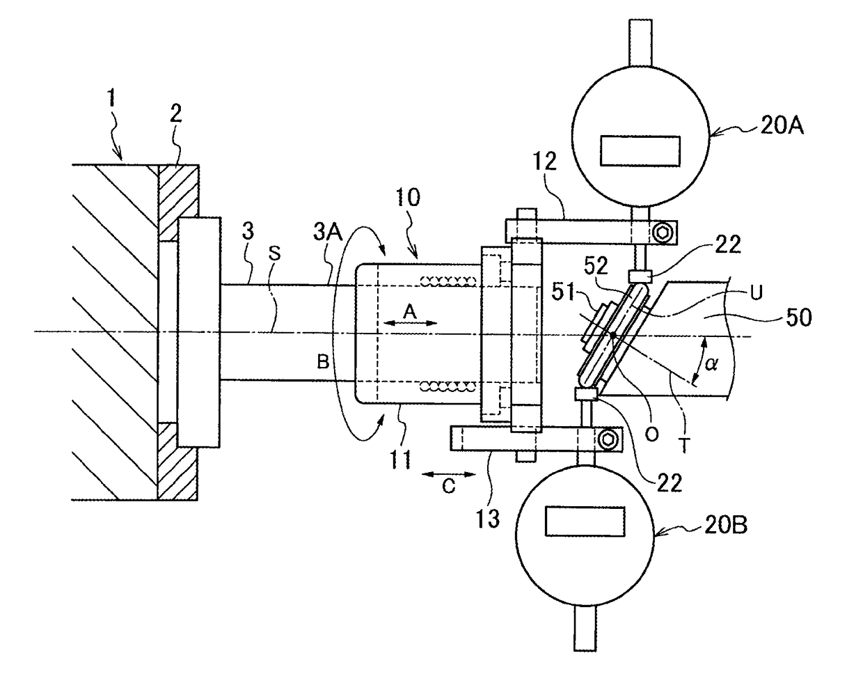
[0022]According to the method for centering the grinding wheel in the thread grinder of the present invention, at a state where the grinding wheel is mounted to the grinding wheel shaft, it is possible to precisely measure a position of the inclined grinding wheel by simultaneously bringing the probes of the two measuring instruments into contact with the two edge parts of the grinding wheel in the inclined direction, from a radial direction orthogonal to the axis of the main shaft. Therefore, it is not necessary to perform a cumbersome operation of replacing a dedicated measuring jig and a grinding wheel. Also, there is no concern that the measuring precision is deteriorated due to the replacing operation, and the centering can be precisely performed with a simple measuring operation.
[0023]Also, according to the measurement deice for centering the grinding wheel in the thread grinder of the present invention, it is possible to simply and precisely perform the centering of the inclined grinding wheel with the grinding wheel being mounted to the grinding wheel shaft, just by using the centering master and the measuring unit having the two measuring instruments attached to the cylindrical body.

Problems solved by technology

Therefore, it is necessary to perform a cumbersome operation of replacing the measurement jig and the grinding wheel, which may deteriorate the measuring precision during the replacing operation.

Method used


Image

  • Method for centering grinding wheel in thread grinder and measurement device for centering
  • Method for centering grinding wheel in thread grinder and measurement device for centering
  • Method for centering grinding wheel in thread grinder and measurement device for centering

Examples


Embodiment Construction

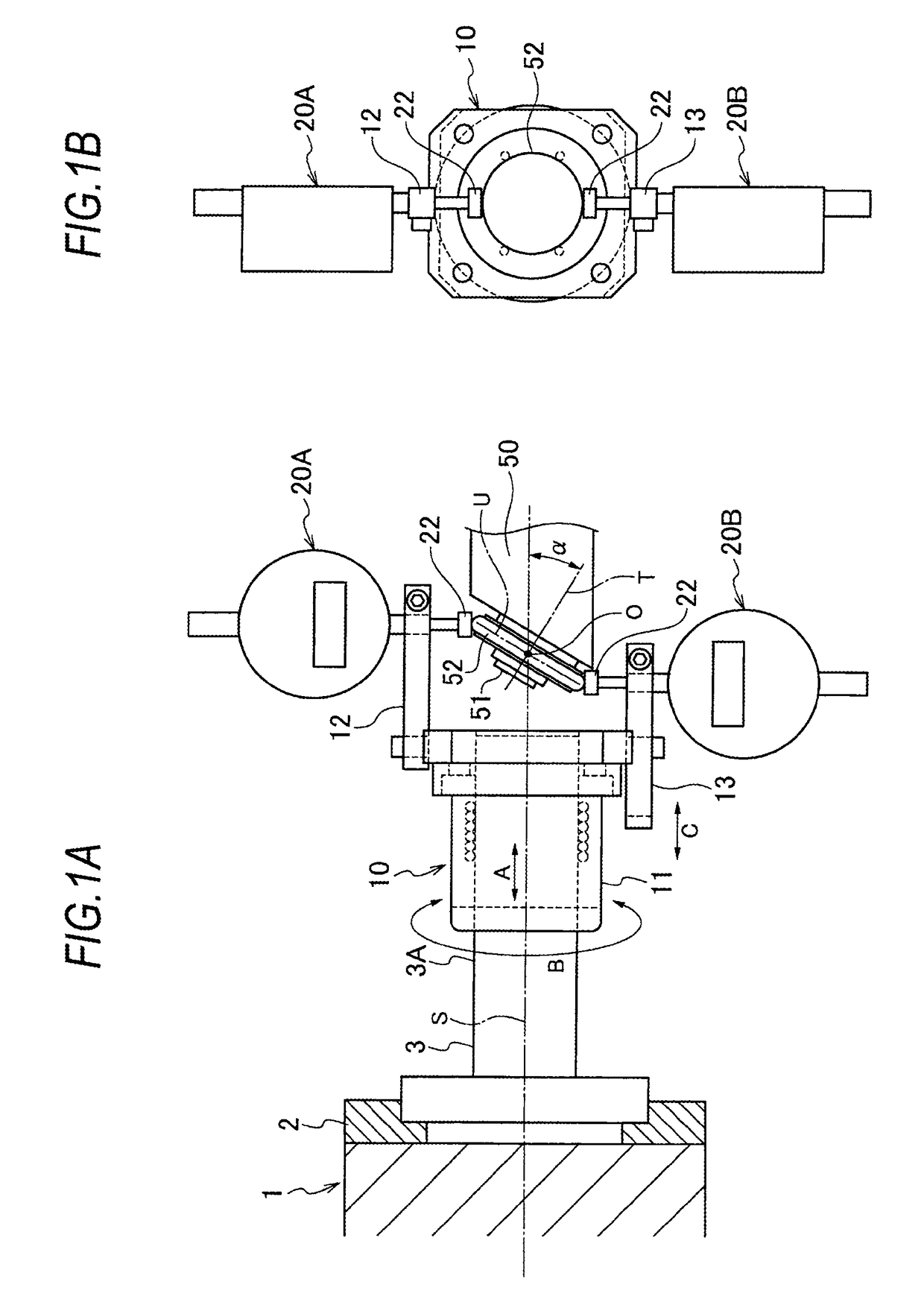
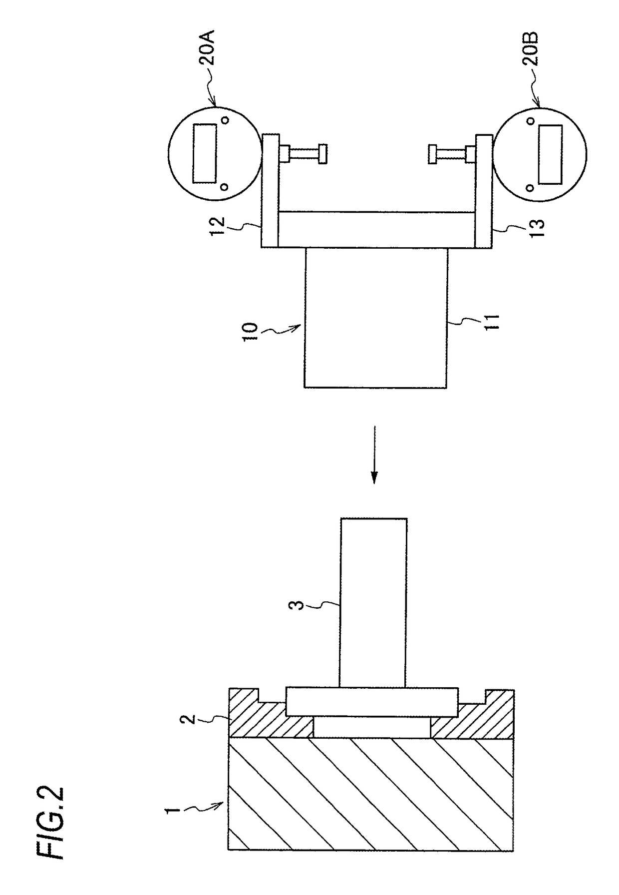
[0030]Hereinafter, an embodiment of the present invention will be described based on the drawings. FIGS. 1A and 1B are views illustrating a centering method of the embodiment, and FIGS. 2 to 5 illustrate processes of the centering method.

[0031]As shown in FIG. 1, a thread grinder has a main shaft 1 rotatably supported to a main shaft board (not shown), and a grinding spindle 50 supported to a grinding wheel board (not shown) to face the main shaft 1 in an axis direction. The main shaft 1 is configured to be rotatable around a horizontal axis S, and a workpiece (not shown) is mounted to the main shaft 1. A grinding wheel shaft 51 is rotatably supported to a tip portion of the grinding spindle 50, and a disc-shaped grinding wheel 52 is attached to a tip portion of the grinding wheel shaft 51.

[0032]The grinding wheel 52 is configured to grind a thread groove on a cylindrical inner surface of the workpiece attached to the main shaft 1. Therefore, a rotation axis T of the grinding wheel ...


PUM

PropertyMeasurementUnit
displacementaaaaaaaaaa
angleaaaaaaaaaa
timeaaaaaaaaaa

Abstract

In a thread grinder which grinds a thread grove on an inner surface of a workpiece while a rotation axis of a grinding wheel shaft is inclined with respect to an axis of a main shaft, a centering master which has a cylindrical outer surface is mounted to the main shaft. A measuring unit including two measuring instruments such that probes can contact two edges of a grinding wheel is mounted to the centering master. The origins of the measuring instruments are set by the probes contacting the cylindrical outer surface of the centering master. The measuring unit is moved in the axial direction of the centering master to bring the probes of the two measuring instruments into contact with the edges of the grinding wheel, respectively. The position of the grinding wheel shaft is adjusted such that measured values obtained by measuring instruments become same.

Description

TECHNICAL FIELD[0001]The present invention relates to a method for centering a grinding wheel in a thread grinder and a measurement device for centering used in employing the method.BACKGROUND ART[0002]In a thread grinder configured to grind a thread groove on a cylindrical inner surface of a workpiece such as a thread groove of a ball nut, a grinding wheel is attached to a tip of a grinding wheel shaft, the workpiece is attached to a main shaft facing the grinding wheel shaft, and a rotation axis of the grinding wheel shaft is inclined with respect to an axis of the main shaft in accordance with a lead angle of the thread groove. In the thread grinder, the centering of the grinding wheel needs to be performed with respect to the workpiece before the grinding.[0003]For example, Patent Document 1 discloses a conventional centering method in which a spherical measurement member is attached to a grinding wheel attaching position on the axis of the grinding wheel shaft inclined with res...

Claims


Application Information

Patent Timeline
Patent Type & Authority Patents(United States)
IPC IPC(8): B23P19/10G01B5/14B24B41/04B24B49/10B23G1/38B23G1/48G01B5/252
CPCB23P19/10B23G1/38B23G1/48B24B41/04B24B49/10G01B5/14G01B5/252G01B2210/44
Inventor IGARASHI, KIYOSHI
Owner NSK LTD
Learn More