
Measuring apparatus and sensor unit for same

a technology of measuring apparatus and sensor unit, which is applied in the direction of measurement devices, instruments, scientific instruments, etc., can solve the problems of measuring error, measurement accuracy decline, and measurement error in the vertical position measurement of the interface, and achieve high measuring accuracy and deterioration of measuring accuracy due to displacement of the sensor uni

Inactive Publication Date: 2008-11-11
FUJIFILM HLDG CORP +1
View PDF9 Cites 0 Cited by
  • Summary
  • Abstract
  • Description
  • Claims
  • Application Information

AI Technical Summary

Benefits of technology

The present invention provides a measuring apparatus that can suppress deterioration of measuring accuracy due to displacement of the sensor unit. The apparatus includes a light source, a sensor unit, a light beam projecting means, a refractive index information obtaining means, a displacement measuring means, and a position adjustment means. The sensor unit holds a thin film layer, a sample holding portion, and a reference surface for position measurement. The light beam enters the sensor unit and impinges upon the interface between the upper surface of the dielectric block and the thin film layer at an angle of incidence to satisfy total internal reflection conditions. The refractive index information is obtained by measuring the refractive index or the change of refractive index at the interface caused by reaction of a sensing material with the analyte or by detecting the change in the refractive index due to reaction of the sensing material with the analyte. The position adjustment means mechanically adjusts the reference surface to its predetermined position. The apparatus can measure the refractive index information or change in refractive index caused by the analyte, and can detect the reaction of the sensing material with the analyte or the change in the interference fringe in the light beam. The technical effect of the invention is to provide a measuring apparatus with high accuracy and reliability for position measurement and analysis of samples.

Problems solved by technology

Conventionally, there has been a problem that the position of the interface changes each time the same sensor unit is mounted on the measuring portion, which can result in a measuring error.
However, these inventor's investigation has revealed that even if the vertical position of the sensor unit is adjusted on the basis of the vertical displacement of the outer bottom surface of the sensor unit, there remains a measuring error (an error produced when the state of light reflected in total internal reflection is measured) due to vertical displacement of the interface.
That is, the difference in the vertical direction between the position of the outer bottom surface of the sensor unit and the position of the interface (which is an actual surface of measurement) causes an error in measurement of the vertical position of the interface due to thermal expansion of the sensor unit in response to change in temperature.

Method used


Image

  • Measuring apparatus and sensor unit for same
  • Measuring apparatus and sensor unit for same
  • Measuring apparatus and sensor unit for same

Examples


first embodiment

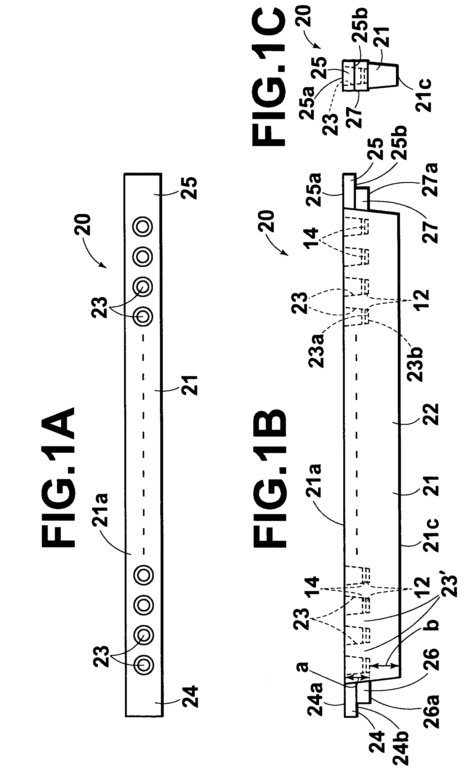
[0148]In FIGS. 1A to 1C, a sensor unit 20 in accordance with the present invention is provided with a body 21 formed of an elongated transparent dielectric material and a plurality of (e.g., 16) sample wells 23 are formed in the body 21 in a predetermined depth a to open in the upper surface 21a of the body 21. The sample wells 23 are arranged in a row and metal film 12 is coated on the inner bottom surface 23a of each of the sample wells 23 by deposition. That is, the body 21 comprises a dielectric block 22 transparent to a light beam (to be described later) and a sample holding portion 23′ which forms the side surface of each sample well 23, which are formed integrally with each other, and the upper surface of the dielectric block 22 forms the inner bottom surface 23a of each of the sample wells 23. Accordingly, the metal film 12 coated on the inner bottom surface 23a of each of the sample wells 23 is metal film coated on the upper surface of the dielectric block 22, and the inter...

second embodiment

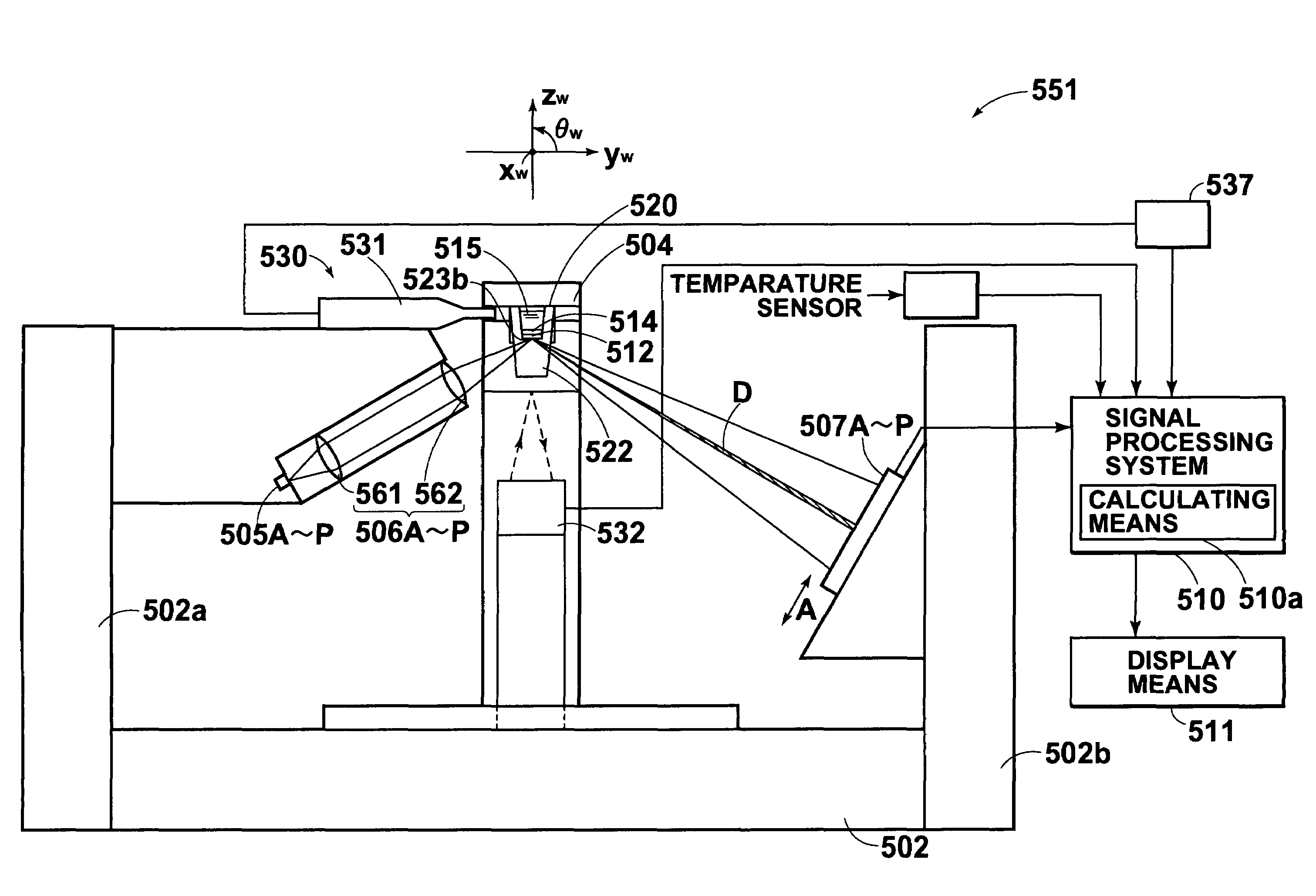
[0193]The surface plasmon resonance sensor 51 differs from that of the second embodiment shown in FIG. 2 only in that the surface plasmon resonance sensor 51 of this embodiment is provided, in place of the position adjustment means, with a calculating means 10a which obtains change in the attenuation angle due to displacement of the interface and calculates a corrected measured value corrected to compensate for the change in the attenuation angle due to displacement of the interface.

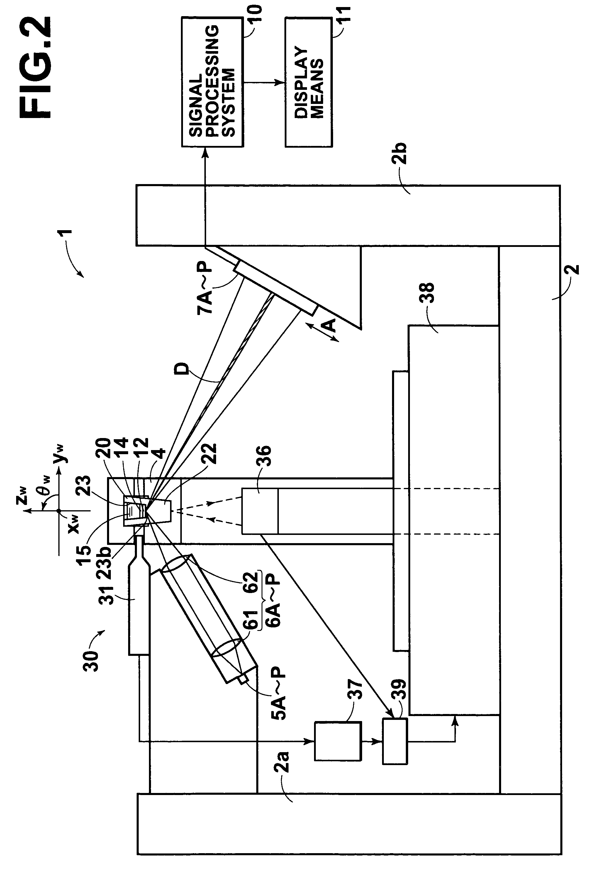
[0194]The surface plasmon resonance sensor 51 of this embodiment corrects the measured value to compensate for the change in the attenuation angle due to displacement of the interface in the following manner. As in the second embodiment, the displacement measuring means 30 measures the position of a sensor unit 20 (the reference position) upon measurement before reaction on the sensor unit 20.

[0195]Then the displacement measuring means 30 obtains the displacements of the sensor unit 20 along the Xw axis,...

eighth embodiment

[0225]FIG. 12 is a cross-sectional view of a surface plasmon resonance sensor in accordance with the present invention. FIG. 13 is a front view schematically showing the arrangement of the sensor unit and the displacement measuring means in the sensor. FIGS. 14A to 14C are a plan view, a front view and a side view schematically showing the positional relation between the sensor unit and the electrostatic probes and the optical angle displacement meter in the surface plasmon resonance sensor. FIG. 15 is an enlarged view of the part of the sensor unit shown in FIG. 14B.

[0226]The sensor unit 520 employed in the surface plasmon resonance sensor 501 of this embodiment will be described first. The sensor unit 520 is provided with a body 521 formed of an elongated transparent dielectric material and a plurality of (e.g., 16) sample wells 523 are formed in the body 521 in a predetermined depth a to open in the upper surface 521a of the body 521. The sample wells 523 are arranged in a row an...


PUM

PropertyMeasurementUnit
reflection angleaaaaaaaaaa
diameteraaaaaaaaaa
diameteraaaaaaaaaa

Abstract

A sensor unit includes a dielectric block, a thin film layer and a reference surface. The thin film layer is formed on the upper surface of the dielectric block and the reference surface is coplanar with the upper surface of the dielectric block. The sensor unit is held in a predetermined position. A light beam is caused to enter the dielectric block to impinge upon the interface between the upper surface of the dielectric block and the thin film layer so that total internal reflection conditions are satisfied at the interface. Information on an analyte on the thin film layer is obtained on the basis of the light beam reflected at the interface. Displacement of the interface is measured by measuring displacement of the reference surface and the position of the sensor unit is adjusted according to the displacement of the reference surface.

Description

BACKGROUND OF THE INVENTION[0001]1. Field of the Invention[0002]This invention relates to a measuring apparatus such as a surface plasmon resonance sensor for analyzing a material in a sample on the basis of generation of surface plasmon, and to a sensor unit for the measuring apparatus.[0003]2. Description of the Related Art[0004]In metal, free electrons vibrate in a group to generate compression waves called plasma waves. The compression waves generated in a metal surface are quantized into surface plasmon.[0005]There have been proposed various surface plasmon resonance sensors for quantitatively analyzing a material in a sample utilizing a phenomenon that such surface plasmon is excited by light waves. Among those, one employing a system called “Kretschmann configuration” is best known. See, for instance, Japanese Unexamined Patent Publication No. 6(1994)-167443.[0006]The surface plasmon resonance sensor using the Kretschmann configuration basically comprises a dielectric block s...

Claims


Application Information

Patent Timeline
Patent Type & Authority Patents(United States)
IPC IPC(8): G01N21/55
CPCG01N21/553
Inventor KUNUKI, YOSHIYUKISHIMIZU, HITOSHIKIMURA, TOSHIHITO
Owner FUJIFILM HLDG CORP
Learn More