Shape detecting apparatus

a technology of shape detection and detecting equipment, which is applied in the direction of instruments, measuring devices, apparatus for force/torque/work measurement, etc., to achieve the effect of small weight of the entire looper device, high resistance to aging deterioration, and easy operation

Active Publication Date: 2005-11-22
IHI CORP
View PDF14 Cites 0 Cited by
  • Summary
  • Abstract
  • Description
  • Claims
  • Application Information

AI Technical Summary

Benefits of technology

[0049]At a sliding portion of the above-mentioned shape detecting unit is provided with a seal member to prevent scale, fluids, etc. from entering from outside.
[0050]Taking advantage of this configuration, the fulcrum of rotation and the power measuring point (load measuring point) can be prevented from being exposed, so the shape detecting unit can be made highly resistant to aging deterioration and worsening of measurement accuracy even in an adverse environment.
[0051]In addition, since the shape detecting unit can be small and light, the weight of the entire looper device can also be small while preventing an increase of GD2, therefore, the response time to a looper control command can be kept short.

Problems solved by technology

However, the aforementioned conventional shape detecting apparatus involve the following problems.(1) Normally at a hot rolling line, a looper apparatus is installed to control tensions.
If a shape detecting function has to be added to an existing looper apparatus, the above-mentioned conventional shape detecting apparatus need to replace the whole equipment.(2) Because a load cell is arranged in the looper arm, the same number of looper arms as the number of the divided rolls is required, resulting therefore in a large weight and GD2 of the entire looper, so the looper cannot quickly respond to a control command.(3) Because of a long looper arm (lever framework length), if the width of a roll is made small, the lateral toughness thereof is lost (small tread length), the roll may deteriorate in the life or be damaged due to a lateral shifting force of a rolled plate.(4) Because the rotation fulcrum and the dynamic force measuring point (load measuring point) of the lever framework are exposed, the equipment might be subject to aging and aggravation in measuring accuracy in an adverse environment.(5) If the width of a rolled plate is less than one half of the roll width, the shape measuring roll may tilt by a moment acting, and detection accuracy become lower.(6) The inner periphery and the bearing of the measuring roll directly contact each other, so heat can be easily transferred from outside the roll, resulting in deterioration of bearing life or damage thereof due to a temperature rise.(7) Because a measuring roll corresponds to a load cell, if a load cell fails, measurements stop.(8) A measuring roll contacts a rolled plate and is driven by the material.
If the roll is quickly accelerated from a stopped state, it may slip and flaws the rolled plate and make unevenly wearing the roll.
Once an uneven wear is produced, it is quickly accelerated, and the roll soon becomes unrotatable.
Also, unless the roll is rotating, the roll is cooled unevenly with cooling water, resulting in uneven distribution of temperatures on each part of the roll, so the roll may deform and the aforementioned problems occur.(9) The measuring system can be affected easily by temperatures of a rolled plate, therefore, a measurement error may be caused because of temperature variations.

Method used


Image

  • Shape detecting apparatus
  • Shape detecting apparatus
  • Shape detecting apparatus

Examples


Embodiment Construction

[0061]Preferred embodiments of the present invention are described referring to the attached drawings. All common members in each figure are identified with the same numbers.

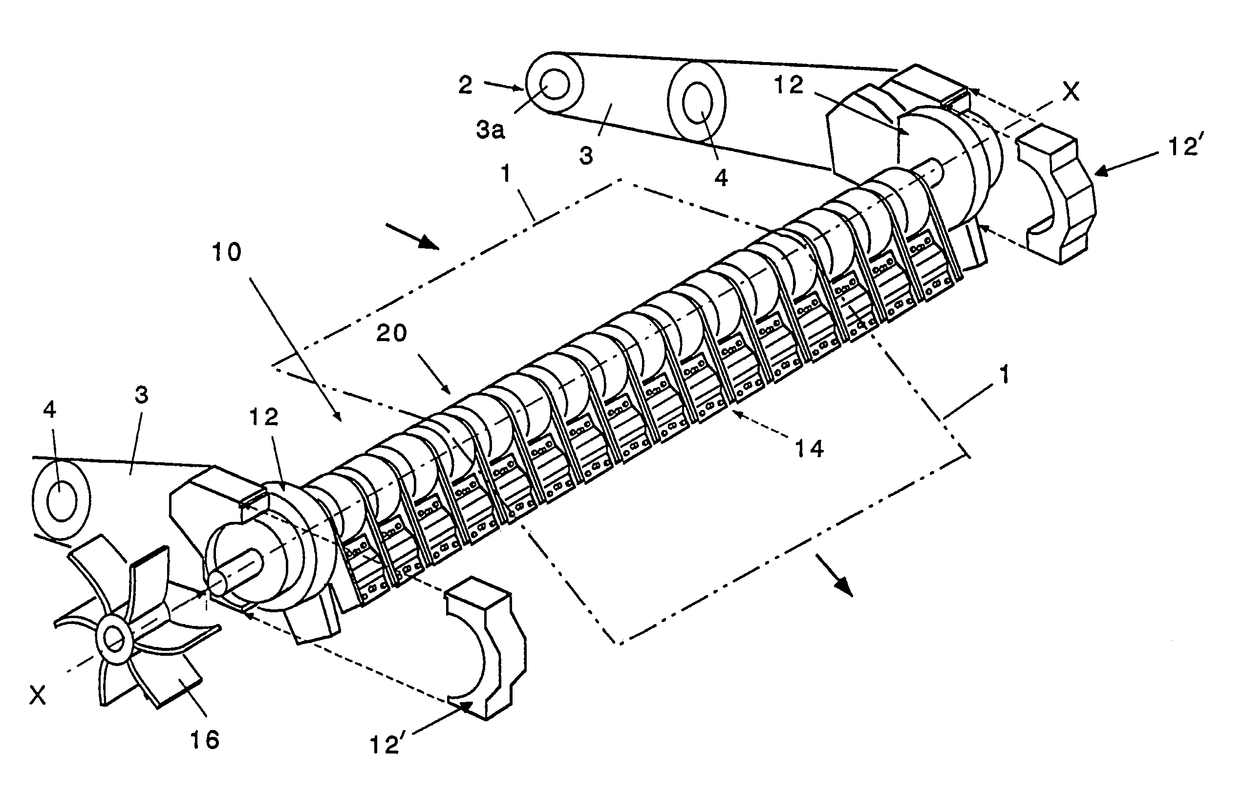
[0062]FIG. 6 is a general isometric view of a shape detecting apparatus according to the present invention. In FIG. 6, the shape detecting apparatus 10 according to the present invention is configured installable by replacing a looper roll (not illustrated) of a looper device 2 that controls the tension of a rolled plate 1. Looper device 2, in this example, is provided with a pair of left and right looper arms 3 that support both ends of the looper roll, and load cells 4 are installed between a fulcrum 3a for supporting looper arm 3 and one end that supports the looper roll, and detect force acting on the looper roll. Therefore, this looper device 2 can detect the force acting on the entire shape detecting apparatus 10 using load cells 4 even when the looper roll is replaced with the shape detecting apparatus 10...


PUM

PropertyMeasurementUnit
tensionaaaaaaaaaa
moment of rotationaaaaaaaaaa
forceaaaaaaaaaa

Abstract

A shape detecting apparatus for controlling the tension of a rolled plate, is composed of a pair of fixing members, a supporting frame and a plurality of shape detecting units. The shape detecting units are fixed detachably in a close proximity of the supporting frame in the lateral direction. The shape detecting units are each composed of cylindrical divided rolls in contact with the rolled plate, a fixed member fixed on the supporting frame, an arm member of which one end supports the divided roll rotatably, and of which the other end is fixed on the fixed member, and a load detector for detecting a moment of rotation acting on the arm member.

Description

BACKGROUND OF THE INVENTION[0001]1. Technical Field of the Invention[0002]The present invention relates to a shape detecting apparatus for detecting the distribution of tensions in the lateral direction at a hot rolling line.[0003]2. Description of the Related Art[0004]As a means for detecting the distribution of lateral tensions at a rolling line, Patent Literatures 1 to 5 have been applied heretofore.[0005]The “Shape control apparatus” of [Patent Literature 1] is shown in FIGS. 1A and 1B. A roller 51 is installed rotatably at the tip portion of a torsion bar 52 using a pin 53, and a pin 54 is equipped at the base portion of this torsion bar 52 and is fixed to a bracket 55. On a fixing portion 56 of the bracket 55, a strain-measuring gauge, e.g. a strain gauge 57 is attached to compose a tension detect element 58. In FIG. 1B, 59 is a lead wire to conduct an electric signal (detection signal) from strain gauge 57.[0006]The “Shape detecting apparatus” of [Patent Literature 2] is show...

Claims


Application Information

Patent Timeline
Patent Type & Authority Patents(United States)
IPC IPC(8): B21B38/02B21B38/00B21C51/00B21B38/06G01L5/04B21B37/00G01L5/10
CPCB21B38/02G01L5/10B21C51/00B21B38/06
Inventor IDE, KENICHI
Owner IHI CORP
Why Eureka
Try Eureka