Method of removing nitrogen oxides from the exhaust gas of a lean-burn internal combustion engine and exhaust-gas purification system therefor

a technology of internal combustion engine and nitrogen oxide, which is applied in the direction of exhaust treatment, engine components, mechanical equipment, etc., can solve the problems of affecting the efficiency of the selective catalytic reduction of platinum-containing catalysts, the range of operation of platinum-containing catalysts for selective catalytic reduction is limited towards high temperatures, and the emission of nitrogen oxides from lean-burn internal combustion engines. , to achieve the effect of simplifying the regeneration of the particulate filter

Active Publication Date: 2008-01-01
UMICORE AG & CO KG
View PDF19 Cites 37 Cited by
  • Summary
  • Abstract
  • Description
  • Claims
  • Application Information

AI Technical Summary

Benefits of technology

[0010]Thus, there continues to be a demand for a method of removing the nitrogen oxides contained in the exhaust gas of lean-burn internal combustion engines in a wide range of operating temperatures between about 150 to over 550° C. It is the object of the present invention to provide such

Problems solved by technology

While the exhaust-gas purification in gasoline engines has largely been solved by the use of three-way catalytic converters, the particulate and nitrogen-oxide emissions from lean-burn internal combustion engines constitute the main problem.
While the sensitivity to sulfur and the required long-term stability represent two critical issues in the NOx adsorber technologies, the SCR

Method used


Image

  • Method of removing nitrogen oxides from the exhaust gas of a lean-burn internal combustion engine and exhaust-gas purification system therefor
  • Method of removing nitrogen oxides from the exhaust gas of a lean-burn internal combustion engine and exhaust-gas purification system therefor
  • Method of removing nitrogen oxides from the exhaust gas of a lean-burn internal combustion engine and exhaust-gas purification system therefor

Examples


example 1

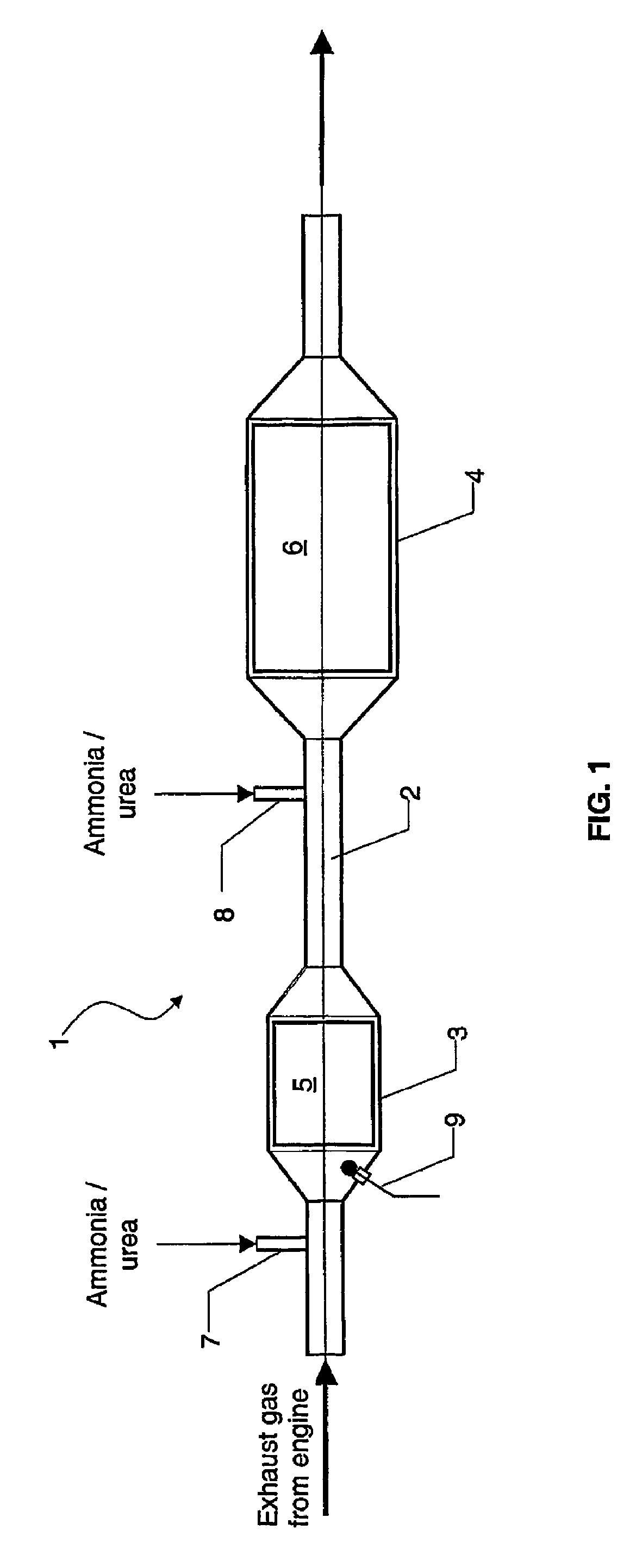
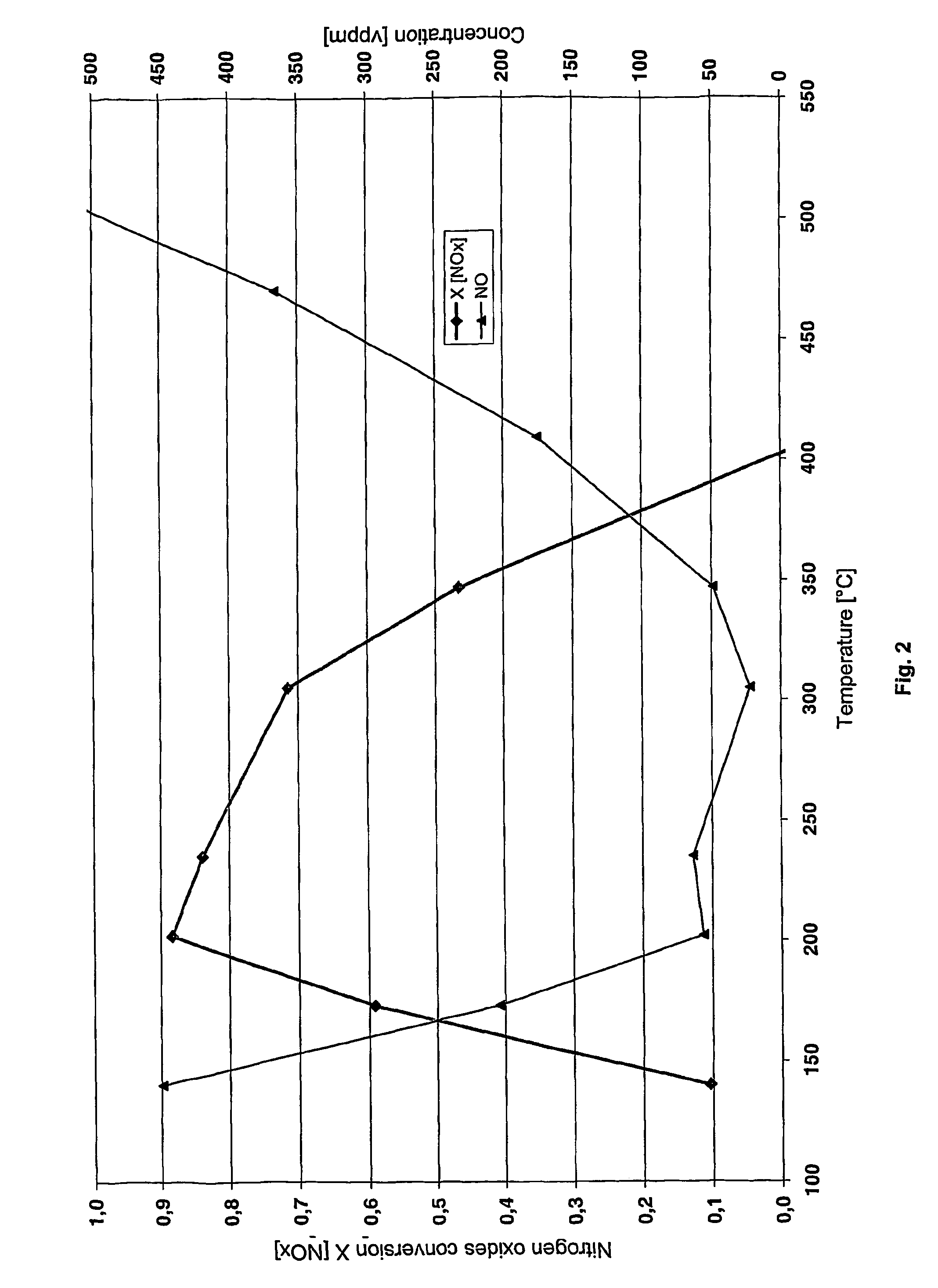
[0049]This example also investigated the series connection of an oxidizing catalyst and an SCR catalyst. In this case, however, the ammonia needed for the selective catalytic reduction was added to the model gas mixture upstream of the oxidizing catalyst at temperatures below 250° C., and to the model gas mixture between the oxidizing catalyst and the SCR catalyst at exhaust-gas temperatures above 250° C.

[0050]FIG. 5 indicates the associated measuring plots. As shown, the method according to the invention can achieve a nitrogen oxides conversion rate of more than 80% for a very wide temperature range from 200° C. to above 500° C.

example 2

[0051]In order to demonstrate the active regeneration of a particulate filter by burning ammonia on the filter, a particulate filter made of silicon carbide and having dimensions of 143.76×152.4 mm and a cell density of 31 cm−2 (5.66″×61″, 200 cpsi) was provided with a catalytic coating which included platinum-activated cerium / zirconium oxide.

[0052]The platinum load of the filter was 5.3 l / g (150 g / ft3). The filter was preloaded with 20.1 g diesel soot and tested for its backpressure on a passenger car engine at various load and temperature stages using metered ammonia addition. It was found that at an exhaust-gas temperature between 350 and 400° C. with metered addition of urea solution at a concentration corresponding to approximately 750 ppm ammonia in the exhaust gas, the filter could be completely regenerated within 15 minutes.


PUM


Abstract

The present invention relates to a method of removing nitrogen oxides from the exhaust gas of a lean-burn internal combustion engine by selective catalytic reduction (SCR) using ammonia. The exhaust gas is routed first over a platinum-containing pre-catalyst and then over an SCR catalyst. The ammonia needed for the selective catalytic reduction is added to the exhaust gas upstream of the pre-catalyst at an exhaust-gas temperature below 250° C., while it is supplied to the exhaust gas between the pre-catalyst and the SCR catalyst at an exhaust gas temperature above 150° C. By adopting this procedure, a very large temperature range for the selective catalytic reduction with high nitrogen conversion rates is obtained.

Description

BACKGROUND OF THE INVENTION[0001]The present invention relates to the removal of nitrogen oxides from the exhaust gas of a lean-burn internal combustion engine and to an exhaust-gas purification system for performing the method. The method relies on the selective catalytic reduction (SCR) of nitrogen oxides using ammonia and on a partial upstream oxidation of nitrogen monoxide to nitrogen dioxide.[0002]Observance of limits planned within the context of EU V in Europe and LEVII in the United States regarding pollutant emissions during operation of internal combustion engines can only be ensured by an active exhaust-gas aftertreatment and exhaust-gas purification, respectively. While the exhaust-gas purification in gasoline engines has largely been solved by the use of three-way catalytic converters, the particulate and nitrogen-oxide emissions from lean-burn internal combustion engines constitute the main problem. In order to convert the nitrogen oxides developed during fuel combusti...

Claims


Application Information

Patent Timeline
IPC IPC(8): F01N3/00B01D53/94F01N3/20F01N13/02
CPCB01D53/9431B01D53/9495F01N3/2066F01N13/009F01N13/0093F01N2610/02Y02T10/24F01N2240/40Y02T10/12
Inventor PFEIFER, MARKUSVAN SETTEN, BARRYSPURK, PAULDEMEL, YVONNEKUHL, TOBIASGIESHOFF, JURGENLOX, EGBERTKREUZER, THOMAS
Owner UMICORE AG & CO KG
Why Eureka
Try Eureka