
Detector for determining a position of at least one object

a technology of at least one object and detector, which is applied in the field of detector, can solve the problems of inability to realize conventional distance measurement technologies easily through optical fiber, inability to accurately measure the distance between light and dark targets, and different results of distance measurements based on light intensity

Pending Publication Date: 2021-06-17
TRINAMIX GMBH
View PDF0 Cites 0 Cited by
  • Summary
  • Abstract
  • Description
  • Claims
  • Application Information

AI Technical Summary

Benefits of technology

The patent text describes a way to replace quadrant photodiodes with close arrangements of separate photodiodes. These photodiodes can be arranged in a rectangular matrix or individually on a circuit board. The separation between the active areas of the photodiodes should be small to avoid optical reflexes that can affect the measurements. The use of a light-absorbing material or plastic separator between the photodiodes can further improve the quality of the optical detector. The technical effects of this patent text include reducing costs, improving measuring accuracy, and minimizing distortions in optical detector arrangements.

Problems solved by technology

However, conventional distance measurement technologies cannot be realized easily through optical fibers.
For example, measurements based on time of flight of photons may not deliver reliable results due to the physical features of multimode fibers.
Moreover, distance measurements based on light intensity may deliver different results for light and dark targets even if targets of both types are positioned at the same distance from the detector since the reflected intensity depends on the reflectivity of the target.
However, DPR may be limited in flexibility when the task is to design a system with a given resolution and a given measurement range.

Method used


Image

  • Detector for determining a position of at least one object
  • Detector for determining a position of at least one object
  • Detector for determining a position of at least one object

Examples


Embodiment Construction

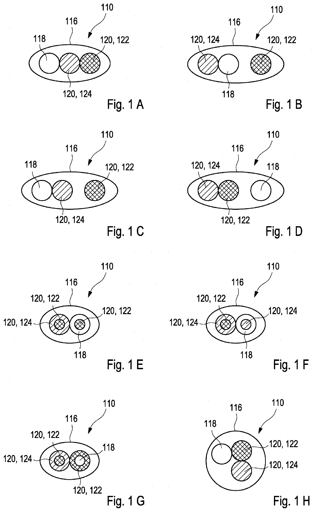
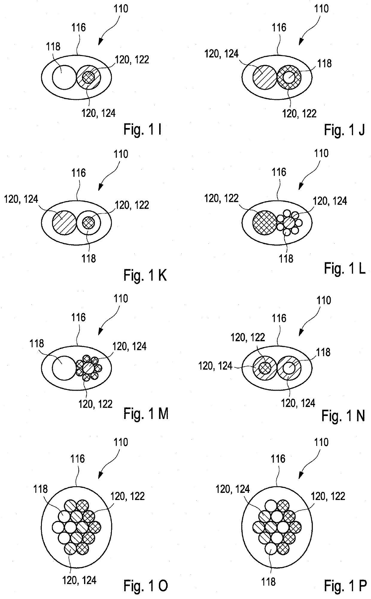
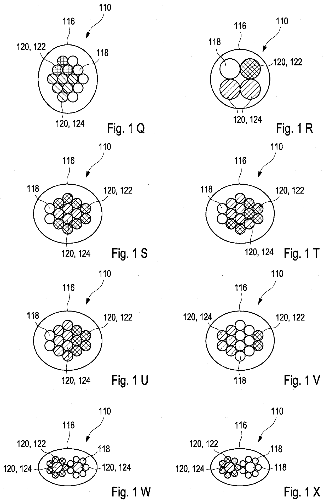
lass="d_n">[0246]FIGS. 1A to JJ show in top view exemplary embodiments of a measurement head 110 of a detector 112 for determining a position of at least one object 114. The measurement head 110 may comprise at least one housing 116, for example at least one metal housing and / or plastic housing. Each of the measurement heads 110 may comprise a plurality of fibers, specifically a plurality of the at least one optical sender fiber 118 and / or at least two optical receiving fibers 120 such as at least one first optical receiving fiber 122 and at least one second optical receiving fiber 124. The first optical receiving fiber 122 may be configured to provide at least one impinging light beam to at least one first optical sensor 126 which is arranged at an exit end of the first optical receiving fiber 122. The second optical receiving fiber 124 may be configured to provide at least one impinging light beam to at least one second optical sensor 128 which is arranged at an exit end of the se...


PUM


Abstract

Described herein is a detector for determining a position of at least one object. The detector includes:at least one transfer device;at least one illumination source adapted to generate at least one light beam for illuminating the object;at least one first optical receiving fiber and at least one second optical receiving fiber;at least two optical sensors; andat least one evaluation device being configured for determining at least one longitudinal coordinate z of the object by evaluating a combined signal Q from the sensor signals.

Description

FIELD OF THE INVENTION[0001]The invention relates to a detector and a method for determining a position of at least one object. The invention further relates to various uses of the detector device. The devices, methods and uses according to the present invention specifically may be employed for example in various areas of daily life, gaming, traffic technology, production technology, security technology, photography such as digital photography or video photography for arts, documentation or technical purposes, medical technology or in the sciences. However, other applications are also possible.PRIOR ART[0002]Fiber optical distance sensors are generally known from prior art. However, conventional distance measurement technologies cannot be realized easily through optical fibers. For example, measurements based on time of flight of photons may not deliver reliable results due to the physical features of multimode fibers. Triangulation generally requires a spatially well resoled array ...

Claims


Application Information

Patent Timeline
IPC IPC(8): G01B11/00G02B6/02G02B6/26
CPCG01B11/002G02B6/262G02B6/02G01B1/00G01B11/24G01B11/026G01S7/4811G01S7/4818G01S17/08G01S17/88
Inventor OEGUEN, CELAL MOHANEBERSPACH, MICHAELSEND, ROBERTBRUDER, INGMAR
Owner TRINAMIX GMBH
Learn More