
Absolute value current-sensing circuit for step-down DC-to-DC converters with integrated power stage

a technology of absolute value current and converter, which is applied in the direction of electric variable regulation, process and machine control, instruments, etc., can solve the problems of reducing the power complicated calibration mechanism to be implemented, and inconvenient operation, so as to achieve accurate measurement of output current and simple circuit implementation, the effect of not affecting the efficiency of dc-to-dc converter

Active Publication Date: 2017-07-18
TELEFON AB LM ERICSSON (PUBL)
View PDF6 Cites 0 Cited by
  • Summary
  • Abstract
  • Description
  • Claims
  • Application Information

AI Technical Summary

Benefits of technology

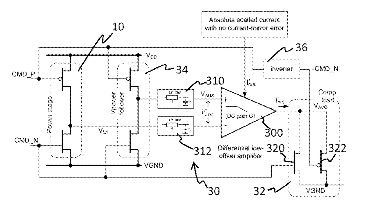
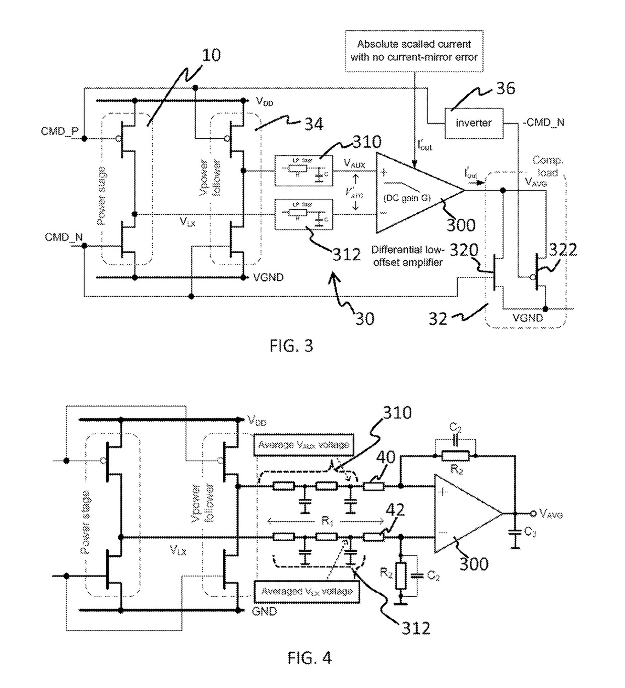
[0007]The object of the present invention is to alleviate at least partly the above mentioned drawbacks. More particularly, embodiments of the invention aim to provide an accurate measurement of the output current of the DC-to-DC converter, with a very simple circuit implementation, without affecting the efficiency of the DC-to-DC converter.
[0009]Because the measured voltage drop on the DC / DC converter power stage is applied on the impedance RComposite, (being the scaled copy of the composite resistance of the power stage), it is possible to obtain an absolute value scaled replica of the output current of the DC-to-DC converter. This allows to measure the output current ÎOUT of the DC-to-DC converter without introducing an external resistance in the output of the DC-to-DC converter, thus avoiding any decrease of the power efficiency of the DC-to-DC converter. No extra passive element in the power path is therefore required.

Problems solved by technology

However, this technique suffers from several drawbacks.
Firstly, the extra resistance introduced in the power path considerably decreases the power efficiency of the DC-to-DC converter.
Secondly, when a parasitic resistance is used for the current sensing, a complicated calibration mechanism is to be implemented, notably for compensating the variation of the resistance, due to the temperature variation.
In practice, it is complicated (say impossible) to compensate perfectly.
This technique is useful for obtaining an absolute value of output current at a given time, but it does not allow obtaining the average value of the output current in a simple manner, which is generally required.
Furthermore, this technique suffers from low accuracy, namely at the high switching frequency of the DC / DC converter.
This is due to the limitation of high-speed operation amplifier inside the current-replica circuit.
Thus, the above mentioned techniques suffer generally from one of the following drawbacks: lack of the absolute value information, high complexity of the circuit for measuring the current, low accuracy or decrease of the power efficiency of the DC-to-DC converter.

Method used


Image

  • Absolute value current-sensing circuit for step-down DC-to-DC converters with integrated power stage
  • Absolute value current-sensing circuit for step-down DC-to-DC converters with integrated power stage
  • Absolute value current-sensing circuit for step-down DC-to-DC converters with integrated power stage

Examples


Embodiment Construction

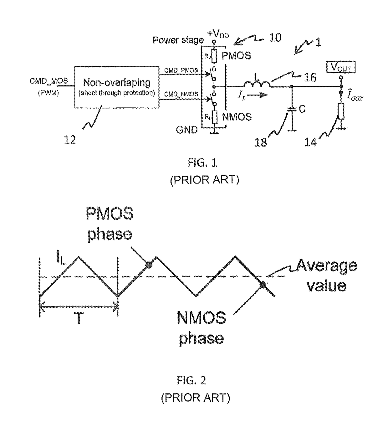
[0039]FIG. 1 shows a simplified schematic of an example of a conventional step-down DC-to-DC converter power stage 1. The power stage 1 represented in FIG. 1 is a step-down or Buck type. It comprises power switches 10 that use two switches. The switches are here a P-MOS and an N-MOS, also referred to as power transistors. The power stage is in this case a transistor power stage. The power transistors may be P and N channel Metal-Oxide-Silicon transistors. The power stage supplies energy to an inductor 16 and a capacitor 18. To this aim, power stage is powered by power rails supplying a positive supply voltage VDD and a ground GND (or negative supply voltage VSS). The inductor current is thus controlled by the switches of the power stage 10. The DC-to-DC converter 1 further comprises a PWM (pulse-duration modulation) generator that generates driving commands CMD_MOS of the switches, that is opening or closing the switches. The DC-to-DC power stage further comprises a non-overlapping ...


PUM


Abstract

A system for measuring an output current of a DC-to-DC converter with a transistor power stage includes a voltage measuring circuit and an impedance. The voltage measuring circuit, which is connected to the output of the power stage of the DC-to-DC converter, measures an average voltage drop on impedances of the transistors of the power stage. The impedance, which is connected to an output of the voltage measuring circuit, reproduces the impedances of the transistors of the power stage and is traversed by a scaled version of the current output of the voltage measuring circuit.

Description

CROSS-REFERENCE TO RELATED APPLICATIONS[0001]This application is Continuation Application of International Application No. PCT / EP2013 / 073233, filed on Nov. 7, 2013, which claims priority and benefit from EP Patent Application No. 12306397.6, filed Nov. 12, 2012 and U.S. Provisional Application 61 / 734,085, filed Dec. 6, 2012, the entire contents of which are incorporated herein by reference.FIELD OF THE INVENTION[0002]The invention relates to a system and a method for measuring an output current of a step-down DC-to-DC converter.BACKGROUND OF THE INVENTION[0003]The sensing of the output current presents nowadays a highly required feature in the DC-to-DC converters design, encountered across all SMPS (switched-mode power supply) device manufacturers. Indeed, the knowledge of the DC-to-DC converter output current is required for the platform development (e.g. optimisation of the software allowing the power consumption reduction in e.g. mobile phone platform). Moreover, information abou...

Claims


Application Information

Patent Timeline
Patent Type & Authority Patents(United States)
IPC IPC(8): G01R19/165G01R19/00H02M3/156H02M3/158H02M1/00H02S50/10
CPCG01R19/16552G01R19/0084G01R19/0092H02M3/156H02M3/1588H02M2001/0009H02S50/10Y02B70/1466H02M1/0009Y02B70/10Y02E10/50
Inventor MICHAL, VRATISLAV
Owner TELEFON AB LM ERICSSON (PUBL)
Learn More