Magnetic jack type control element drive mechanism for precision position control of control element assembly

a technology of control element and drive mechanism, which is applied in the direction of nuclear elements, greenhouse gas reduction, nuclear engineering, etc., can solve the problem of not being precise enough to be used, and achieve the effect of improving the position control resolution of the motor assembly

Active Publication Date: 2017-07-18
KEPCO ENGINEERING & CONSTRUCTION COMPANY INC
View PDF21 Cites 0 Cited by
  • Summary
  • Abstract
  • Description
  • Claims
  • Application Information

AI Technical Summary

Benefits of technology

[0022]One or more exemplary embodiments include a magnetic jack type control element drive mechanism for precision position control of the control element assembly, which is applied to a 4-coil type control element drive mechanism to improve a position control resolution of a motor assembly.

Problems solved by technology

However, such a conventional method is not precise enough to be used in a small reactor; therefore, there has been a demand for a control element drive mechanism with precise position control capacity.

Method used


Image

  • Magnetic jack type control element drive mechanism for precision position control of control element assembly
  • Magnetic jack type control element drive mechanism for precision position control of control element assembly
  • Magnetic jack type control element drive mechanism for precision position control of control element assembly

Examples


Embodiment Construction

[0041]Reference will now be made in detail to embodiments, examples of which are illustrated in the accompanying drawings, wherein like reference numerals refer to the like elements throughout. In this regard, the present embodiments may have different forms and should not be construed as being limited to the descriptions set forth herein. Accordingly, the embodiments are merely described below, by referring to the figures, to explain aspects of the present description.

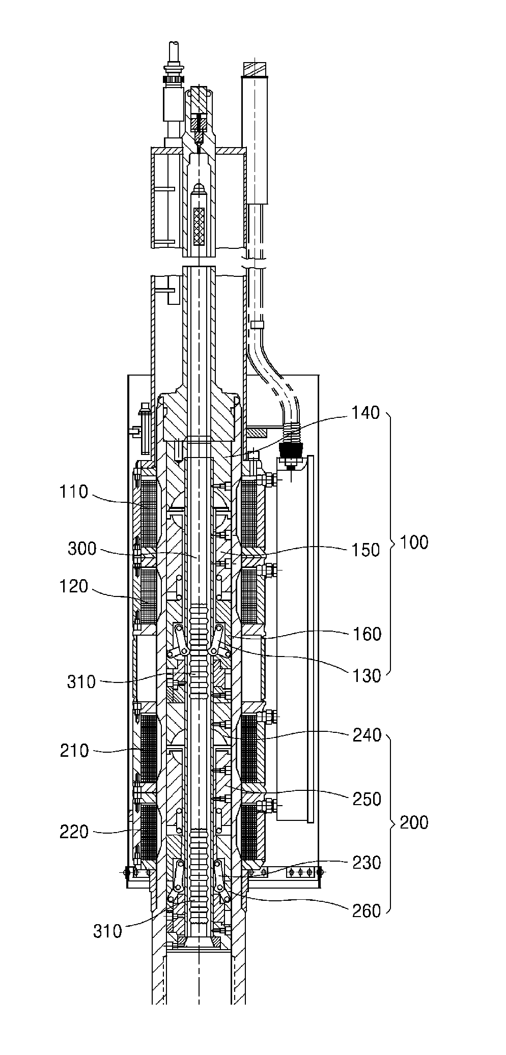
[0042]One or more embodiments of the present invention relates to a magnetic jack type control element drive mechanism which is operated as a 4-coil type. A control element drive mechanism according to an embodiment of the present invention may be applied to a reactor which needs precise position control of a control element, particularly to a small reactor which requires a precise position control capacity in terms of its characteristics.

[0043]Hereinafter, exemplary embodiments of the present invention will be explai...


PUM


Abstract

A magnetic jack type control element drive mechanism for precision position control of a control element assembly, satisfies the following conditions:D1=D2=P+D5;D3=P×2;D4=D3×(N−½), (N is an arbitrary natural number),whereinD1 represents a lift gap of the upper motor assembly;D2 represents a lift gap of the lower motor assembly;D3 represents a space width between tips of adjacent teeth of the drive shaft;D4 represents a gap between an upper latch and a lower latch;P represents pitch that is a distance of ascent or descent of the drive shaft; andD5 represents a margin which is a separation space between the teeth and the upper latch or the lower latch when the upper latch or the lower latch is inserted into the teeth of the drive shaft.

Description

CROSS-REFERENCE TO RELATED PATENT APPLICATION[0001]This application claims the benefit of Korean Patent Application No. 10-2014-0158062, filed on Nov. 13, 2014, in the Korean Intellectual Property Office, the disclosure of which is incorporated herein in its entirety by reference.BACKGROUND OF THE INVENTION[0002]1. Field of the Invention[0003]One or more exemplary embodiments relate to a magnetic jack type control element drive mechanism for precision position control of a control element assembly, and more particularly, to a control element drive mechanism which is applied to a 4-coil magnetic jack type control element drive mechanism to increase resolution of position control of a motor assembly.[0004]The present invention is derived from research conducted as part of the Nuclear Power Core Technology Development Program by the Ministry of Trade, Industry & Energy [Project Serial Number: 20131510101680, Title of Research Project: Development of Top-Mounted ICI System and In-Vessel...

Claims


Application Information

Patent Timeline
Patent Type & Authority Patents(United States)
IPC IPC(8): H02K41/03G21C7/14
CPCG21C7/14H02K41/03H02K41/031Y02E30/39Y02E30/30
Inventor PARK, JIN SEOKJANG, YONG TAELEE, MYOUNG GOOCHANG, SANG GYOONLEE, DAE HEE
Owner KEPCO ENGINEERING & CONSTRUCTION COMPANY INC
Why Eureka
Try Eureka