Display driving module and driving method

A display driver and driver technology, used in static indicators, instruments, etc., can solve the problems of difficulty in realizing the driving circuit and inconsistency of target values, etc., and achieve increased modulation resolution, high modulation resolution, and fine modulation resolution. Effect

Active Publication Date: 2021-05-04
MINIDSN INC
View PDF18 Cites 0 Cited by
  • Summary
  • Abstract
  • Description
  • Claims
  • Application Information

AI Technical Summary

Problems solved by technology

However, the non-ideality of the drive circuit leads to difficulties in implementation. For example, it takes time to switch between different output currents. During this switching time, the output value is different from the ideal value; and for example, the signal rise time and fall time of different target pulse heights are different. , the increase or decrease range and the target pulse height are not necessarily linearly proportional, so that the total output when the pulse width is doubled is different from the total output when the pulse height is doubled, resulting in the modulation result and the total output target value does not match

Method used


Image

  • Display driving module and driving method
  • Display driving module and driving method
  • Display driving module and driving method

Examples


Embodiment Construction

[0039] The technical means adopted by the present invention to achieve the intended invention purpose are further described below in conjunction with the drawings and preferred embodiments of the present invention.

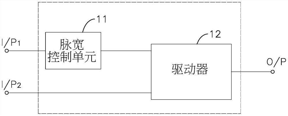
[0040] see figure 1 As shown, the present invention provides a display driver module, including a pulse width control unit 11 and a driver 12, the driver 12 is electrically connected to the pulse width control unit 11, the pulse width control unit 11 receives a pulse width information and according to To generate a pulse width control signal, the driver 12 receives the pulse width control signal and a signal slope information, and the driver 12 generates a driving signal according to the pulse width control signal and the signal slope information.

[0041] Wherein, the driver 12 controls the conduction time of the drive signal according to the pulse width control signal and the signal slope information, and controls the signal rise rate of the drive signal during ...


PUM


Abstract

The present invention relates to a display driving module and a driving method. The display driving module includes a pulse width control unit and a driver. The driver is electrically connected to the pulse width control unit to receive a pulse width control signal, and receives a signal slope information, and generates a signal accordingly. A drive signal, and the driver controls the signal rise rate of the drive signal during the conduction time according to the signal slope information, and controls the conduction time of the drive signal according to the pulse width control signal and the signal slope information; when the drive signal is not within the conduction time When the output target value is reached, and the rising and falling curves are approximately linear, the total output of the driving signal in the working cycle is proportional to the square of the conduction time, which increases the resolution and control range of the total output at low brightness.

Description

technical field [0001] The invention relates to a driving module and a driving method, in particular to a display driving module and a driving method thereof. Background technique [0002] Existing displays generally use pulse width modulation (Pulse Width Modulation; PWM) to control the degree of brightness and darkness recognized by the human eye. By virtue of the persistence of vision of the human eye, when the frequency of brightness and darkness of a light source is greater than one When the critical value is reached, the human eye cannot feel the flicker of the light source. Therefore, in a duty cycle greater than the critical frequency, the total output of the light source of the display is changed by adjusting the percentage of on-time in each duty cycle, so as to Provide human eyes with different brightness. The on-time percentage can be divided into a plurality of minimum on-time unit times by a digital-element on-control signal to generate a total on-time that ac...

Claims


Application Information

Patent Timeline
Patent Type & Authority Patents(China)
IPC IPC(8): G09G3/3208G09G3/36
CPCG09G3/3208G09G3/3648
Inventor 史富洋
Owner MINIDSN INC
Why Eureka
Try Eureka