Bidirectional compression die, and implementation method and application thereof

A technology of lateral compression and longitudinal compression, applied in the field of molds, can solve the problems of unsatisfactory control of microcellular foaming, and achieve the effects of good interchangeability, compact and reasonable overall structure, large flexibility and scope.

Active Publication Date: 2012-11-14
SOUTH CHINA UNIV OF TECH
View PDF8 Cites 7 Cited by
  • Summary
  • Abstract
  • Description
  • Claims
  • Application Information

AI Technical Summary

Problems solved by technology

Similar to the above-mentioned principle analysis, if the microcellular foamed melt is compressed, the comprehensive performance of the microcellular foamed polymer product can be improved; The control is still not ideal, if the two-way compression can be achieved, it will have an important role in promoting the quality of the molded products

Method used


Image

  • Bidirectional compression die, and implementation method and application thereof
  • Bidirectional compression die, and implementation method and application thereof
  • Bidirectional compression die, and implementation method and application thereof

Examples


Embodiment 1

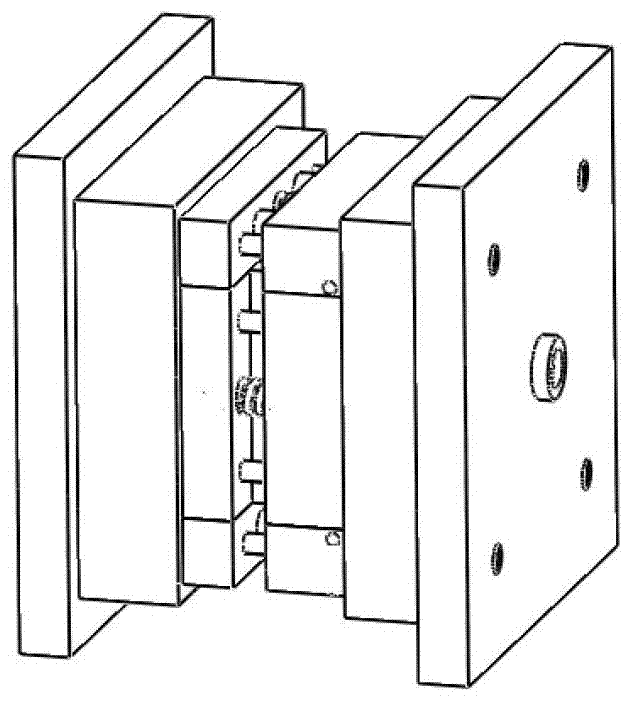
[0048] Figure 2 ~ Figure 4 shows the concrete structure of the present invention, by Figure 2 ~ Figure 4 It can be seen that the two-way compression mold of the present invention includes a movable template 1, a movable mold fixed plate 3, a fixed template 16, a fixed mold fixed plate 15, a cavity block assembly, and a compression block assembly; the cavity block assembly includes a longitudinal cavity block ( 71, 72, 74, 141, 142 and 144) and transverse cavity blocks (73 and 143); the compression block assembly includes a longitudinal compression block 8 and a transverse compression block 9; the fixed mold fixing plate 15, cavity block Assembly and compression block assembly constitutes a closed cavity 23, and through the longitudinal cavity block (71, 72, 74, 141, 142 and 144), the longitudinal compression block 8 and the transverse cavity block (73 and 143), the transverse The relative movement of the compression block 9 in the longitudinal and transverse directions real...

Embodiment 2

[0064] The polymer product is molded according to the two-way compression method described in Example 1, but the transverse compression speed is set to zero, so that the polymer melt 27 in the mold cavity 23 is only subject to longitudinal compression.

Embodiment 3

[0066] The polymer product is molded according to the two-way compression method described in Example 1, but the longitudinal compression speed is set to zero, so that the polymer melt 27 in the mold cavity 23 is only subjected to transverse compression.


PUM


Abstract

The invention provides a bidirectional compression die, which comprises a moving template, a moving die fixing plate, a fixed template, a fixed die fixing plate, a die cavity block component and a compression block component, wherein the die cavity block component comprises longitudinal die cavity blocks and transverse die cavity blocks; the compression block component comprises a longitudinal compression block and a transverse compression block; and the fixed die fixing plate, the die cavity block component and the compression block component form an enclosed die cavity, and the longitudinal die cavity blocks, the longitudinal compression block, the transverse die cavity blocks and the transverse compression block longitudinally and transversely move relative to each other to change the volume of the die cavity. The invention also provides a bidirectional compression method. According to the bidirectional compression method, the longitudinal die cavity blocks, the longitudinal compression block, the transverse die cavity blocks and the transverse compression block are synchronously operated to change the volume of the die cavity both longitudinally and transversely or only longitudinally or transversely. The volume of the die cavity can be changed in longitudinal and transverse two dimensions simultaneously, and unidirectional or bidirectional compression can be realized according to needs to meet the higher compression requirements of a product.

Description

technical field [0001] The invention relates to mold technology, in particular to a bidirectional compression mold and its realization method and application. Background technique [0002] At present, in the process of using molds to shape products, in some cases, it is necessary to compress the molding materials to ensure better product quality. For example, in the traditional injection molding process of polymer material products, the polymer melt is injected into the completely closed mold cavity under high pressure, and the product will warp due to the large residual stress in the molded product. , poor dimensional stability and other issues. Injection compression molding technology can better solve the above problems. In injection compression molding, the melt is first injected into the initially closed cavity, the melt is compressed during the injection process or after the injection, and then in the completely closed cavity Cool and shape. Compared with traditional...

Claims


Application Information

Patent Timeline
Patent Type & Authority Applications(China)
IPC IPC(8): B29C45/56
Inventor 黄汉雄田家栋关伟盛
Owner SOUTH CHINA UNIV OF TECH
Why Eureka
Try Eureka