
Engine-driven generator

a technology of engine and generator, which is applied in the direction of engine components, machines/engines, mechanical equipment, etc., can solve the problems of difficulty in performing a cooling operation in which the cylinder block is cooled, and achieve the effect of increasing efficiency

Active Publication Date: 2017-07-25
HONDA MOTOR CO LTD
View PDF7 Cites 0 Cited by
  • Summary
  • Abstract
  • Description
  • Claims
  • Application Information

AI Technical Summary

Benefits of technology

The patent describes an arrangement for a small engine-driven generator that reduces the size of the engine and increases efficiency. The cylinder of the engine is placed vertically, and an exhaust muffler is placed next to the cylinder block's lateral side. This space allows for the installation of the exhaust muffler, which results in a smaller engine. The fan cover is designed to direct cooling air from the cooling fan to the cylinder block and exhaust muffler, ensuring proper cooling. The muffler blow-off port's opening area can be adjusted to distribute the cooling air properly. This arrangement prevents damage to the exhaust muffler and increases the generator's cooling efficiency.

Problems solved by technology

With this arrangement, it is difficult to perform a cooling operation in which the cylinder block is cooled by cooling air and the exhaust muffler is cooled by the cooling air after having cooled the cylinder block in the same manner as done for the engine-driven generator disclosed in WO2008 / 032414.

Method used


Image

  • Engine-driven generator
  • Engine-driven generator
  • Engine-driven generator

Examples


Embodiment Construction

[0020]A certain preferred structural embodiment of the present invention will be described in greater details below, by way of example only, with reference to the accompanying sheets of drawings. In the drawings, “Fr” and “Rr” are used to refer to a front side or recoil cover side, and a rear side or engine side, respectively.

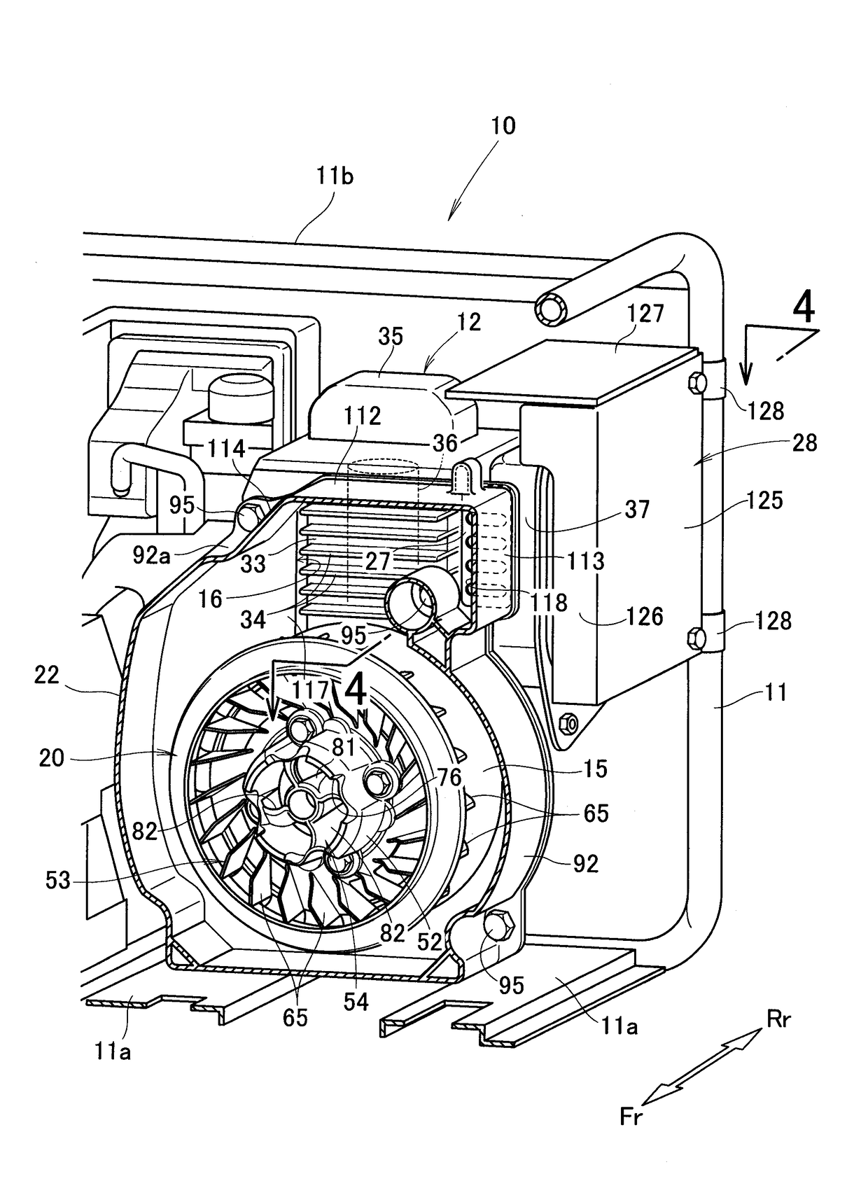
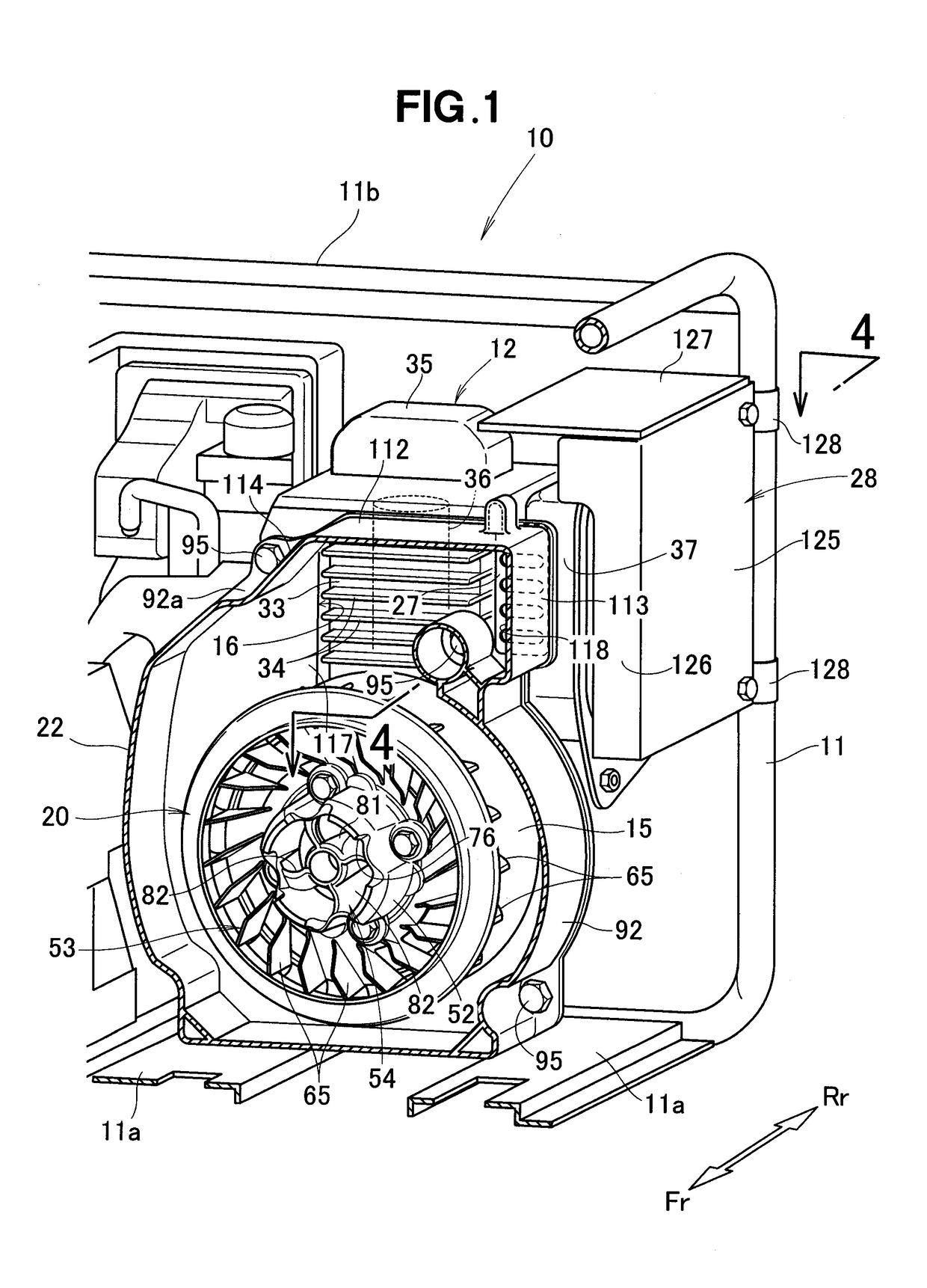
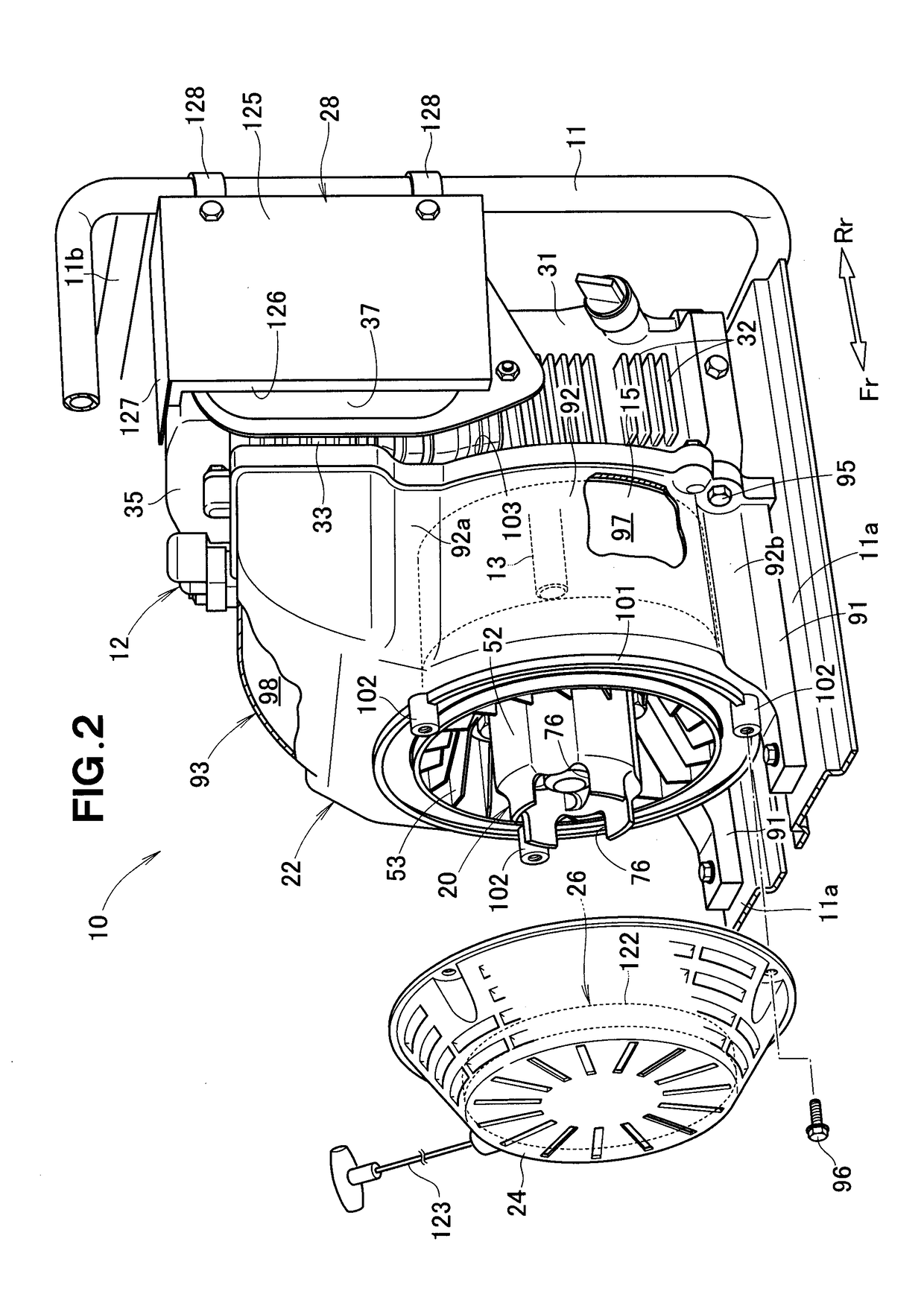
[0021]As shown in FIGS. 1 and 2, an engine-driven generator 10 embodying the present invention includes an engine 12 mounted on a bottom 11a of a frame 11, a generator unit 15 provided in front of the engine 12, a cooling fan 20 connected to a drive shaft of the generator unit 15, a fan cover 22 covering the cooling fan 20 and the generator unit 15.

[0022]The engine-driven generator 10 further includes a recoil cover 24 attached to the fan cover 22, a recoil starter 26 attached to the recoil cover 24, an opening area-adjusting member 27 attached to a rear end portion of the fan cover 22, and a muffler protector 28 for protecting the exhaust muffler 37.

[0023]The ...


PUM


Abstract

An engine-driven generator includes an exhaust muffler disposed adjacent to a lateral side of a cylinder block, a fan cover having an air outlet arranged to face the exhaust muffler and the cylinder block, the fan cover being configured to guide cooling air from a cooling fan directly to the air outlet, and an opening area-adjustment member provided on a muffler blow-off port of the air outlet for adjusting an opening area of the muffler blow-off port.

Description

FIELD OF THE INVENTION[0001]The present invention relates to an engine-driven generator including a generator unit driven by an engine, and an exhaust muffler provided in the vicinity of a cylinder block of the engine.BACKGROUND OF THE INVENTION[0002]Engine-driven generators are known, which includes a cooling fan disposed on one side (hereinafter referred to as “front side”) of an engine and an exhaust muffler disposed on an opposite side (hereinafter referred to as “rear side”) of the engine such that the engine and the exhaust muffler are cooled by cooling air fed from the cooling fan. More specifically, the engine (more particularly, a cylinder block thereof) is cooled by the cooling air fed from the cooling fan, and the exhaust muffler is cooled by the cooling air after having cooled the engine. A typical example of such known engine-driven generators is disclosed in WO2008 / 032414.[0003]In the engine-driven generator disclosed in WO2008 / 032414, the cooling fan is provided on th...

Claims


Application Information

Patent Timeline
Patent Type & Authority Patents(United States)
IPC IPC(8): F01N3/00F01P1/06F02B63/04F01N1/00F01N13/00
CPCF01N13/002F01N1/00F01P1/06F02B63/04F02B63/044F01N2260/022F01N2260/20F01N2590/10
Inventor TAKAHASHI, YUKIKASE, TAKUOSHIMOZONO, KAZUKIYANAI, KIYOMI
Owner HONDA MOTOR CO LTD
Learn More