
Liquid crystal display device and projection-type display device

a display device and liquid crystal technology, applied in the direction of projectors, polarising elements, instruments, etc., can solve the problems of color fading and image quality degradation, image quality degradation, and burning of protective layers, so as to improve the image quality reduce the component count of the projection-type display device, and achieve the effect of reducing the number of light fastness

Inactive Publication Date: 2011-01-18
SONY CORP
View PDF17 Cites 1 Cited by
  • Summary
  • Abstract
  • Description
  • Claims
  • Application Information

AI Technical Summary

Benefits of technology

The present invention provides a liquid crystal display device with improved image quality and reduced component count. The device includes a reflective inorganic polarizer between the drive transistor and pixel electrode, which prevents the returning light from the polarizer from entering the drive transistor. The device also includes a light source, condensing optical system, and projection optical system, which guides the light optically modulated by the liquid crystal display device. The use of a reflective polarizer on both the incident and emitting sides allows for significant downsizing of the set.

Problems solved by technology

However, the organic polarizers 11 and 12 disposed on the incident and emitting sides entails the problems of color fading and image quality degradation with increasing light intensity.
Image quality degradation results from the burning of the protective layer.
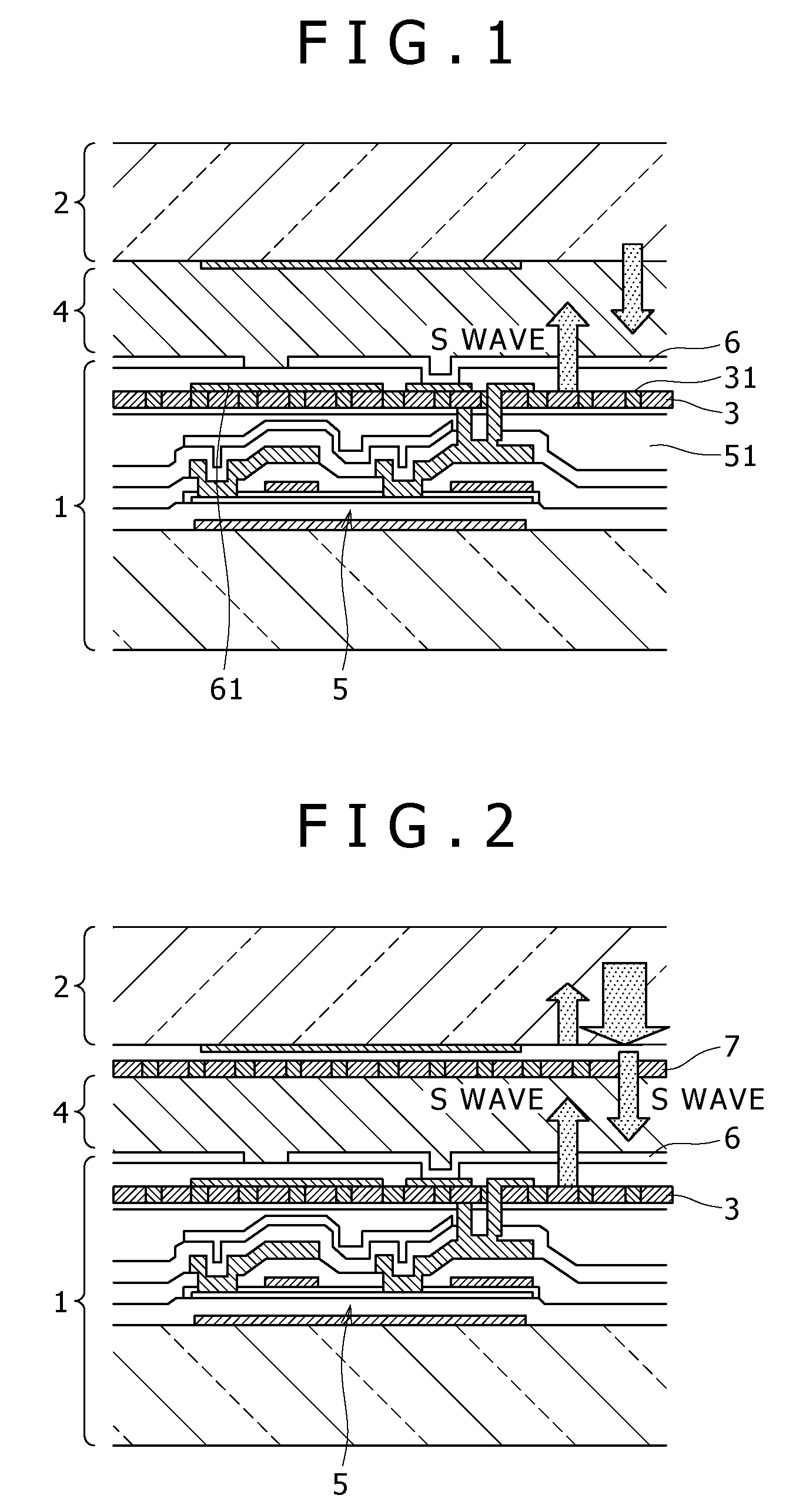
However, a reflective inorganic polarizer 3, if disposed on the emitting side or on the outside of the driving-side substrate 1, adversely affects the image quality as a result of the light returning from the polarizer striking the drive transistor 5, as illustrated in FIG. 8.
However, this solution leads to a large device configuration.
On the other hand, absorptive inorganic polarizers have yet to reach a level of practical utility due to their characteristic problems in the visible range (blue range in particular).

Method used


Image

  • Liquid crystal display device and projection-type display device
  • Liquid crystal display device and projection-type display device
  • Liquid crystal display device and projection-type display device

Examples


Embodiment Construction

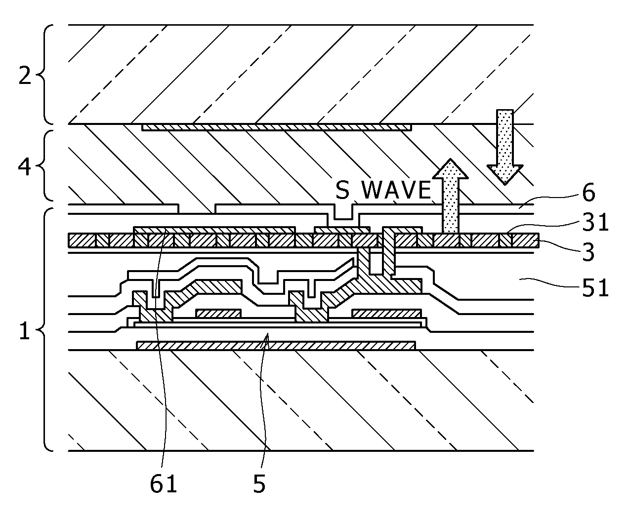
[0022]The preferred embodiment of the present invention will be described below with reference to the accompanying drawings. FIG. 1 is a schematic sectional view describing a liquid crystal display device according to the present embodiment. That is, the liquid crystal display device according to the present embodiment includes the driving-side substrate 1 and opposed-side substrate 2. The drive transistor 5, pixel electrode 6 and orientation film are formed on the driving-side substrate 1. The opposed electrode and orientation film are formed on the opposed-side substrate 2. The liquid crystal display device further includes liquid crystal 4. The liquid crystal 4 is filled between the pixel electrode 6 and opposed electrode with the driving-side substrate 1 and opposed-side substrate 2 attached together. The liquid crystal display device still further includes the reflective inorganic polarizer 3. The reflective inorganic polarizer 3 is formed between the drive transistor 5 and pix...


PUM

PropertyMeasurementUnit
optical stressaaaaaaaaaa
electrical continuityaaaaaaaaaa
voltageaaaaaaaaaa

Abstract

The problem to be solved is to suppress image quality degradation caused by polarizers and provide improved light fastness.To solve the above problem, the embodiment of the present invention is a liquid crystal display device. The liquid crystal display device includes a driving-side substrate 1 on which a drive transistor 5, pixel electrode 6 and orientation film are formed. The liquid crystal display device further includes an opposed-side substrate 2 on which an opposed electrode and orientation film are formed. The liquid crystal display device still further includes liquid crystal 4 filled between the pixel electrode 6 of the driving-side substrate 1 and opposed electrode of the opposed-side substrate 2. The liquid crystal display device still further includes a reflective inorganic polarizer 3 formed between the drive transistor 5 and pixel electrode 6 of the driving-side substrate 1. The embodiment of the present invention is also a projection-type display device using the liquid crystal display device.

Description

TECHNICAL FIELD[0001]The embodiment of the present invention relates to a liquid crystal display device with liquid crystal filled between a driving-side substrate and opposed-side substrate, and to a projection-type display device using the same.BACKGROUND ART[0002]A projection-type display device (projector) using a liquid crystal display device has an absorptive organic polarizer on the incident and emitting sides. That is, FIG. 7 is a schematic sectional view describing a related art liquid crystal display device. In this liquid crystal display device, a drive transistor 5, pixel electrode 6 and orientation film are formed on a driving-side substrate 1. In the same device, an opposed electrode and orientation film are formed on an opposed-side substrate 2. The liquid crystal display device is formed by first attaching the driving-side and opposed-side substrates 1 and 2 together with a predetermined gap therebetween and then filling liquid crystal 4 between the pixel electrode 6...

Claims


Application Information

Patent Timeline
Patent Type & Authority Patents(United States)
IPC IPC(8): G02F1/1335
CPCG02F1/133536G03B21/00G02F2001/133565G02F2001/133548G03B21/006G02F1/133548G02F1/133565G02B5/30G02F1/1335
Inventor TATEMORI, YUMIKOTSUBOTA, HIROYOSHIABE, FUMIAKI
Owner SONY CORP
Learn More