
Air intake structure of straddle type vehicle

a technology of air intake structure and straddle type, which is applied in the direction of machine/engine, combustion-air/fuel-air treatment, separation process, etc., can solve the problems of complicated operations such as replacement of elements and the like, and achieve the effect of easy attachment and removal, easy operation, and easy attachment and removal

Active Publication Date: 2017-07-25
HONDA MOTOR CO LTD
View PDF7 Cites 2 Cited by
  • Summary
  • Abstract
  • Description
  • Claims
  • Application Information

AI Technical Summary

Benefits of technology

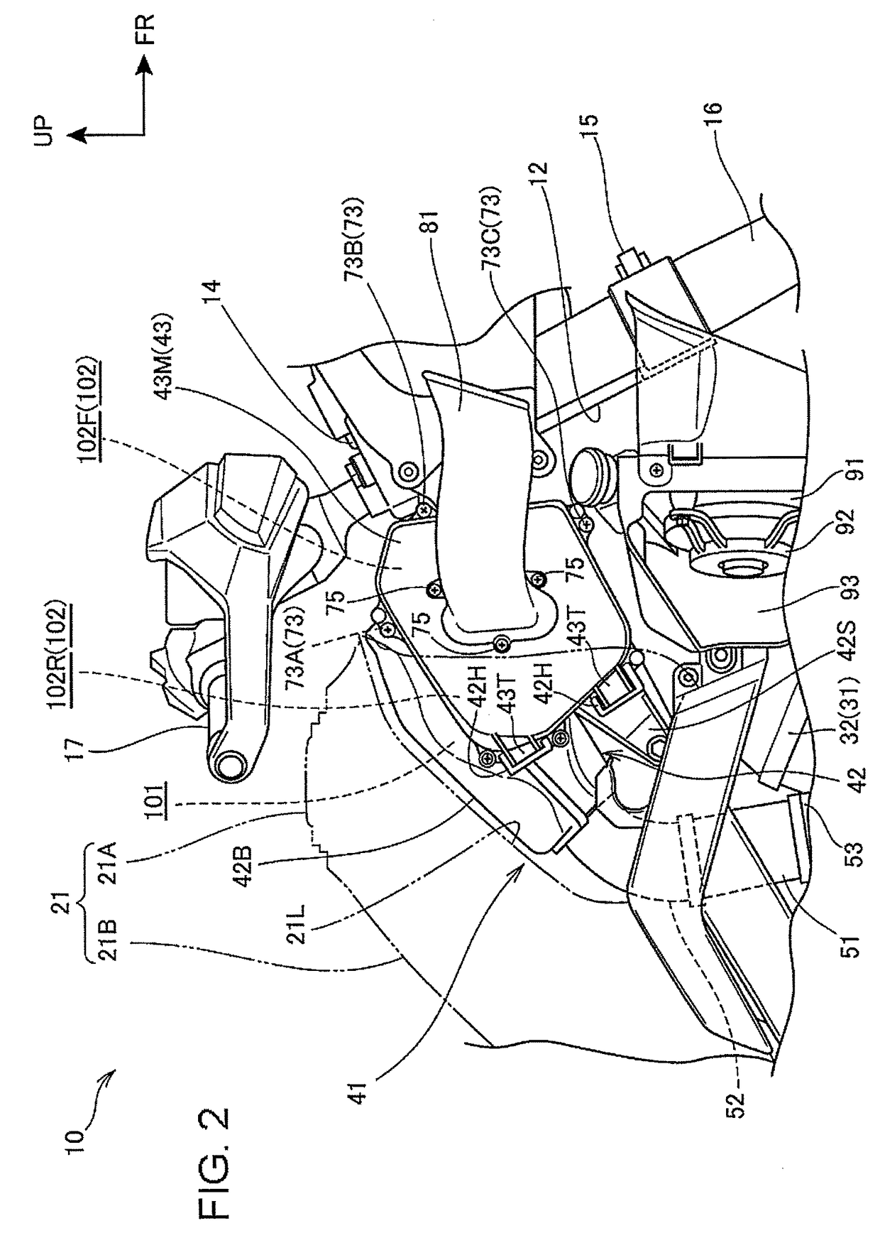
[0008]According to an embodiment of the present invention, the capacity of the main chamber can be ensured by making use of the space between the main frames, and the capacity of the sub-chamber also can be ensured by making use of the space formed between each of the outside wall surfaces of the main frames and the inside wall surface of the fuel tank. In addition, since the fastening means for fastening the element lid which covers the element from the outside in the vehicle width direction is located forwardly of the tank member in the side view of the vehicle, the element lid can be removed without removing the tank member. Therefore, the maintenance of the element can be carried out without removing the tank member while ensuring the capacity of the air cleaner.
[0019]According to an embodiment of the present invention, the air cleaner is configured to form the main chamber and the air cleaner case having the left and right straddling sections each of which extends left and right from the main chamber and straddles the left and right main frames from above. The left and right straddling sections have the openings which open outwardly in the vehicle width direction. The element is arranged in each of the openings, and the element lid is fastened in such a way as to close each of the openings to form the pair of left and right sub-chambers. Therefore, the left and right sub-chambers can be easily formed and the component parts can be easily reduced.

Problems solved by technology

In the conventional construction, however, in order for having access to the element it is necessary to remove the fuel tank, whereby operations such as replacement of the element and the like become complicated.

Method used


Image

  • Air intake structure of straddle type vehicle
  • Air intake structure of straddle type vehicle
  • Air intake structure of straddle type vehicle

Examples


Embodiment Construction

[0028]The embodiment of the present invention will be described hereunder with reference to accompanying drawings. In the following description, the orientation such as front, rear, left, right, upper and lower shall be identical to the orientation of a vehicle body unless otherwise described. In addition, in each drawing, a reference character FR designates a forward direction of the vehicle body, a reference character UP designates an upper direction of the vehicle body and a reference character LE designates a left direction of the vehicle body.

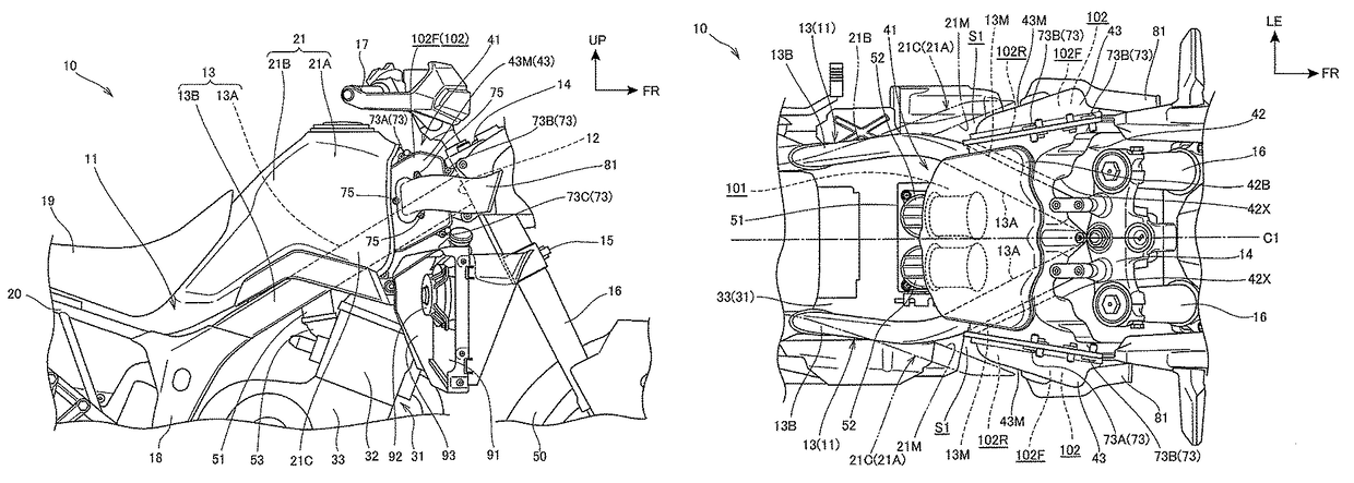
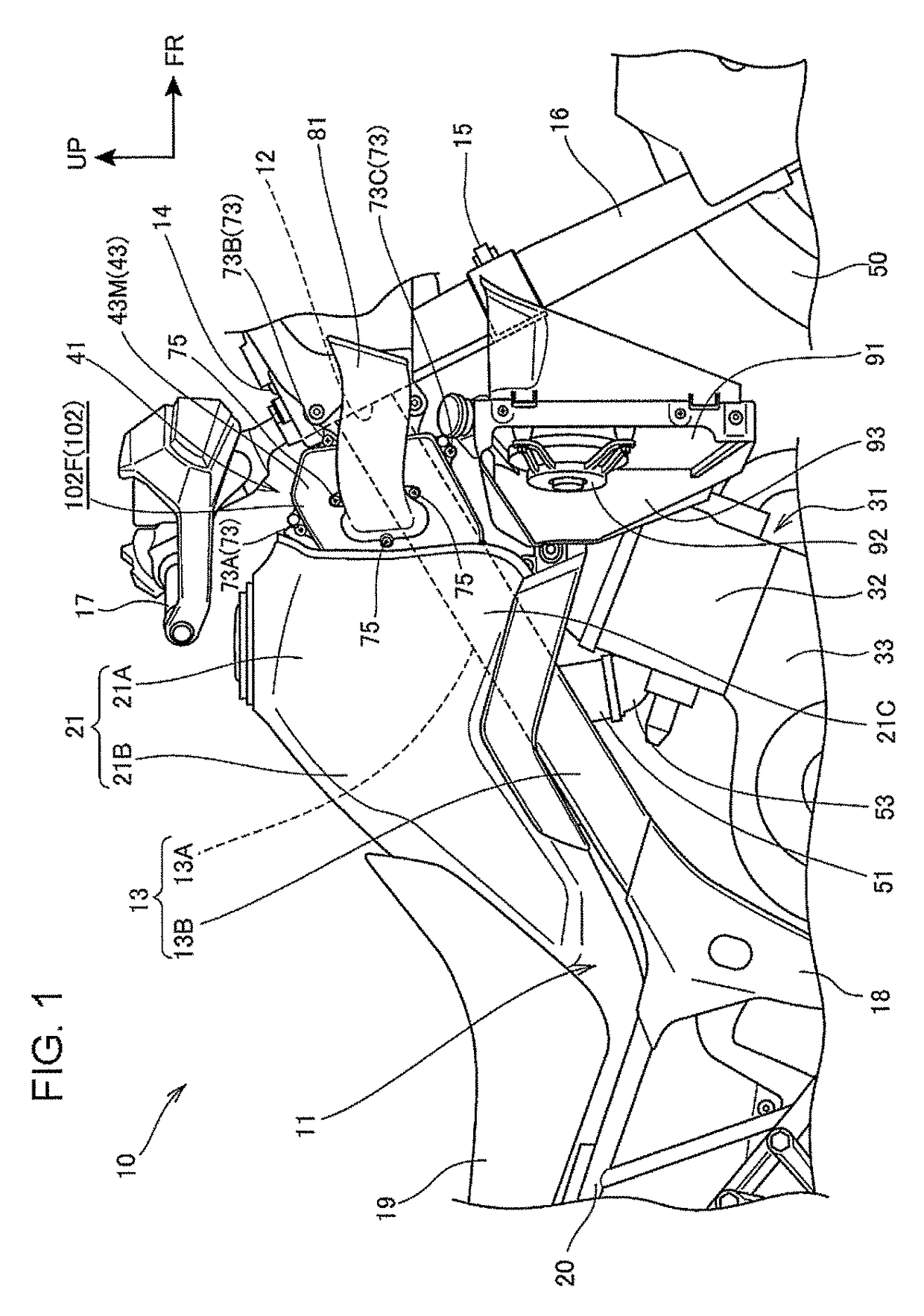
[0029]FIG. 1 is a right side view of a front part of a two-wheeled motorcycle in accordance with an embodiment of the present invention.

[0030]A vehicle body frame 11 of this motorcycle 10 includes a pair of left and right main frames 13 that extends rearwardly and downwardly from a head pipe 12. A fuel tank (tank member) 21 is located above the main frames 13 with an engine 31 being supported below the main frames 13.

[0031]A pair of left a...


PUM

PropertyMeasurementUnit
widthaaaaaaaaaa
rigidityaaaaaaaaaa
internal structureaaaaaaaaaa

Abstract

An air cleaner is arranged below a fuel tank of a straddle type disposed above left and right main frames. The air cleaner includes a main chamber which is located between the main frames, and a sub-chamber which is located on the outside in the vehicle width direction of the main frames. A rear section of the sub-chamber and a rear section of the element within the sub-chamber are located in a space formed between each outside wall surface of the main frames and an inside wall surface of the fuel tank. A front section of the sub-chamber and a front section of the element project forwardly of the fuel tank in a side view of the vehicle. The front section of the sub-chamber is provided with the fastening means for fastening the side cover (the element lid) which covers the element from the outside in the vehicle width direction.

Description

BACKGROUND OF THE INVENTION[0001]1. Field of the Invention[0002]The present invention relates to an air intake structure of a straddle type vehicle in which an air cleaner is arranged below a tank member disposed above a pair of left and right main frames.[0003]2. Description of Background Art[0004]In a straddle type vehicle, such as two-wheeled motorcycle and the like, an air cleaner is known wherein the air cleaner is arranged below a fuel tank which is disposed above a pair of left and right main frames. In this type of vehicle, at least a portion of the air cleaner is located between the left and right frames, and an element is arranged in the upward and downward direction in such a way so as to partition an interior of the air cleaner. See, for example, Japanese Patent Application Laid-Open Publication No. 2009-83810.[0005]In the conventional construction, however, in order for having access to the element it is necessary to remove the fuel tank, whereby operations such as repl...

Claims


Application Information

Patent Timeline
Patent Type & Authority Patents(United States)
IPC IPC(8): B60K13/02F02M35/04F02M35/10F02M35/02B01D46/00F02M35/16
CPCF02M35/162B01D46/0005B60K13/02F02M35/0201F02M35/048F02M35/10006B01D2279/60
Inventor KOYAMA, SHINYAYAMASAKI, SATORU
Owner HONDA MOTOR CO LTD
Learn More