
Hand piece for dental or surgical applications

a handpiece and surgical technology, applied in the field of handpieces, can solve the problems of affecting affecting the function of the handpiece, so as to prolong the life of the handpiece, not only the push button, but the entire handpi

Active Publication Date: 2017-08-01
BIEN AIR HLDG SA
View PDF2 Cites 0 Cited by
  • Summary
  • Abstract
  • Description
  • Claims
  • Application Information

AI Technical Summary

Benefits of technology

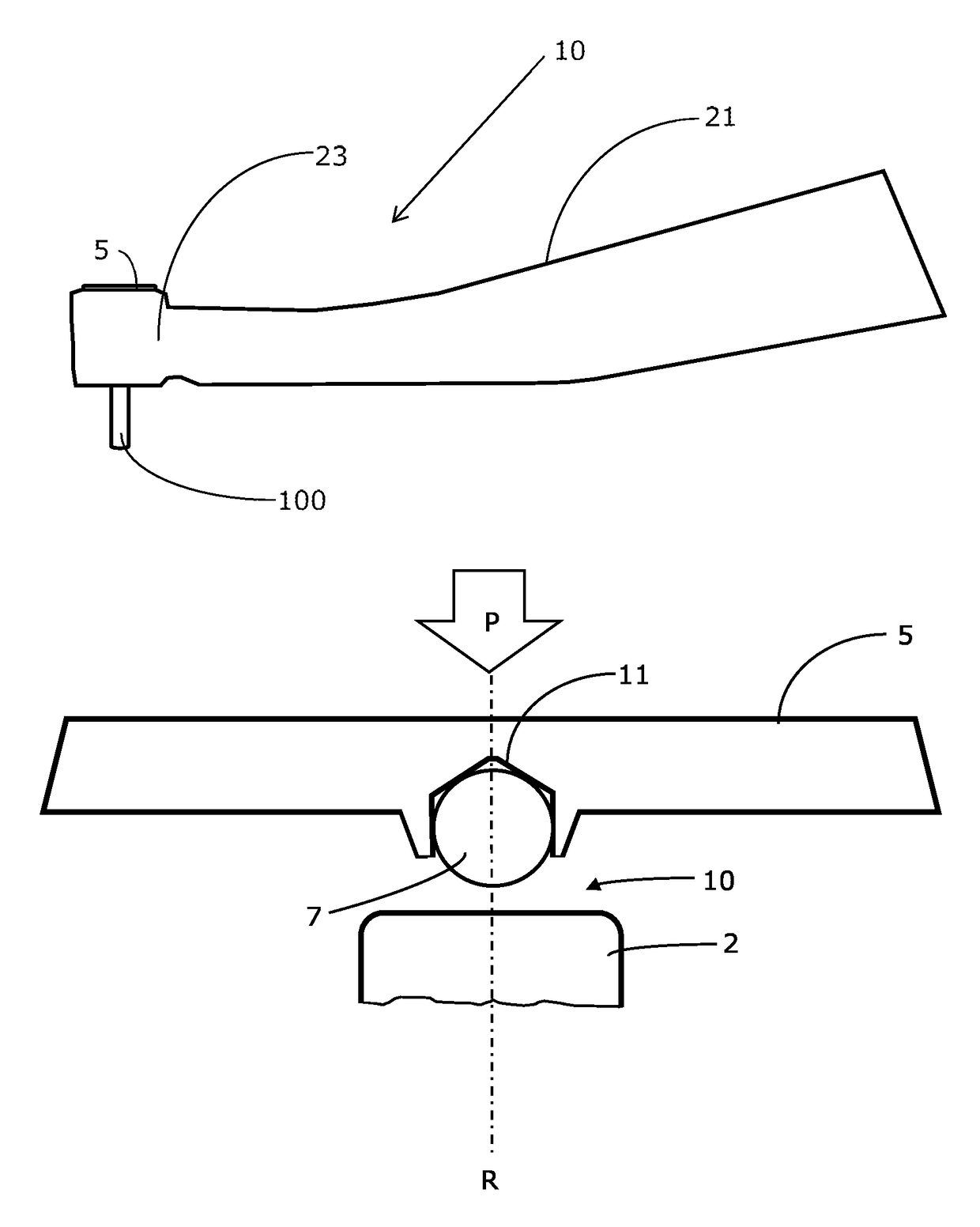
[0012]The most important advantage of the present invention is that by providing efficient heat insulation between the rotating part of the chuck and the push button, injuries due to overheating of the push button upon accidental depression or misuse thereof can be avoided. A further advantage of the present invention over the known solutions, is that the wear of the heat insulating elements is substantially reduced thereby prolonging the lifetime of not only the push button, but the entire handpiece.

Problems solved by technology

If this is done using the handpiece itself, there is a risk that the push button is depressed during the procedure while the bur is rotating, thus creating friction between the rotating part of the chuck and the non-rotating push button.
With a rotation speed in the range between 40,000 and 400,000 rpm, heat builds up very quickly with the risk of burns to the soft tissue.
Nevertheless, the friction will end up generating heat in the hard metal washer which transmits the heat directly to the push button and potentially to the patient.
Finally, the stainless steel ball will wear out with time, increasing the contact surface with the push button.
However, in addition to being an expensive solution, the ball bearing is used in a way that leads to fast wear-out of the ball bearing;Providing the chuck mechanism with a rounded end in hard metal.
However, due to the large geometry, the heat protection of this design is very limited.

Method used


Image

  • Hand piece for dental or surgical applications
  • Hand piece for dental or surgical applications
  • Hand piece for dental or surgical applications

Examples


Embodiment Construction

[0021]Certain terms will be used in this patent application, the formulation of which should not be interpreted to be limited by the specific term chosen, but as to relate to the general concept behind the specific term.

[0022]Following, the invention shall be described with reference to the illustrating figures.

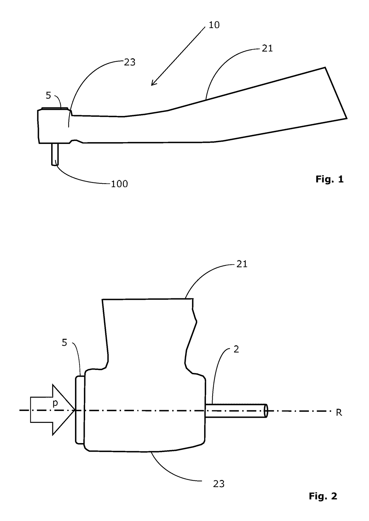
[0023]FIG. 1 shows a side view of a handpiece 10 for dental or surgical applications identifying its main sections, namely the grip section 21 and the head section 23. The handpiece is configured to receive a tool 100, such as a drilling bur.

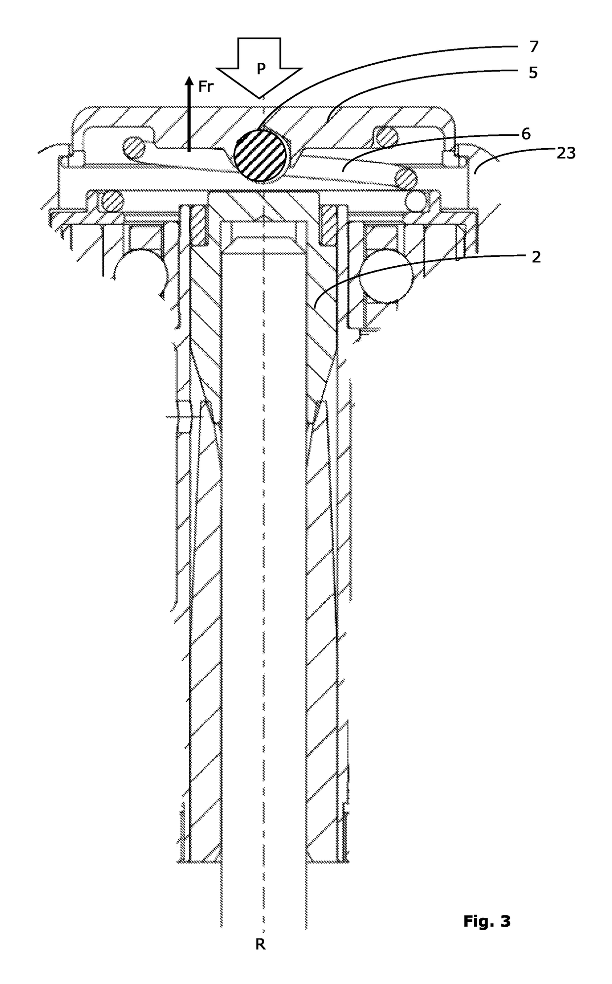
[0024]Further details of the head section 23 of the handpiece 10 are shown on the exploded partial side view of FIG. 2. As depicted, the head section 23 receives the chuck 2 (only an extension thereof being visible on FIG. 2) and a push button 5, the chuck 2 being arranged to rotate about the rotation axis R together with the tool 100 it is configured to receive.

[0025]In accordance with the present invention, a so-called 3D spherical elem...


PUM


Abstract

A handpiece for dental or surgical applications has a chuck for rotatably clamping a tool such as a bur, the chuck being drivingly connectable to a drive mechanism such as to rotate the tool about a rotation axis thereof, a push button operatively connected to the chuck, configured to release the tool from the chuck upon depressing the push button, a spherical element, preferably a ball, fitted within or mounted at the push button, arranged and configured such that, when the push button is depressed, the spherical element enters into contact with the chuck, the spherical element being of a material with a high hardness on the Vickers scale of >2000.

Description

FIELD OF THE INVENTION[0001]The present invention relates to handpieces, in particular handpieces for dental or surgical applications.BACKGROUND OF THE INVENTION[0002]Handpieces for dental or surgical applications are used for a multitude of clinical procedures. Carrying out these procedures is done with a large selection of burs. Changing the burs during a procedure or in between procedures is done through a mechanism in the head of the handpiece which is activated by a push button. To release / introduce a bur, the push button is depressed (pressed down) to activate a release mechanism of the chuck. During a procedure, in particular a dental procedure, the handpiece is introduced in the oral cavity, for example to remove caries. To access a tooth from the vestibular side, the soft tissue (cheek) must be pushed away, in order to create the space necessary for the handpiece and the bur. If this is done using the handpiece itself, there is a risk that the push button is depressed durin...

Claims


Application Information

Patent Timeline
Patent Type & Authority Patents(United States)
IPC IPC(8): A61C3/00A61C1/14A61B17/16
CPCA61B17/162A61C1/141A61C1/144A61B17/1673
Inventor JUILLERAT, SEBASTIEN
Owner BIEN AIR HLDG SA
Learn More