Charging device for vehicle
a charging device and vehicle technology, applied in hybrid vehicles, engine-driven generators, transportation and packaging, etc., can solve the problems of user trouble, timer setting cannot be cancelled, instant charging cannot be carried out, etc., and achieve the effect of burdening users with troublesome burdens
- Summary
- Abstract
- Description
- Claims
- Application Information
AI Technical Summary
Benefits of technology
Problems solved by technology
Method used
Image


Examples
first embodiment
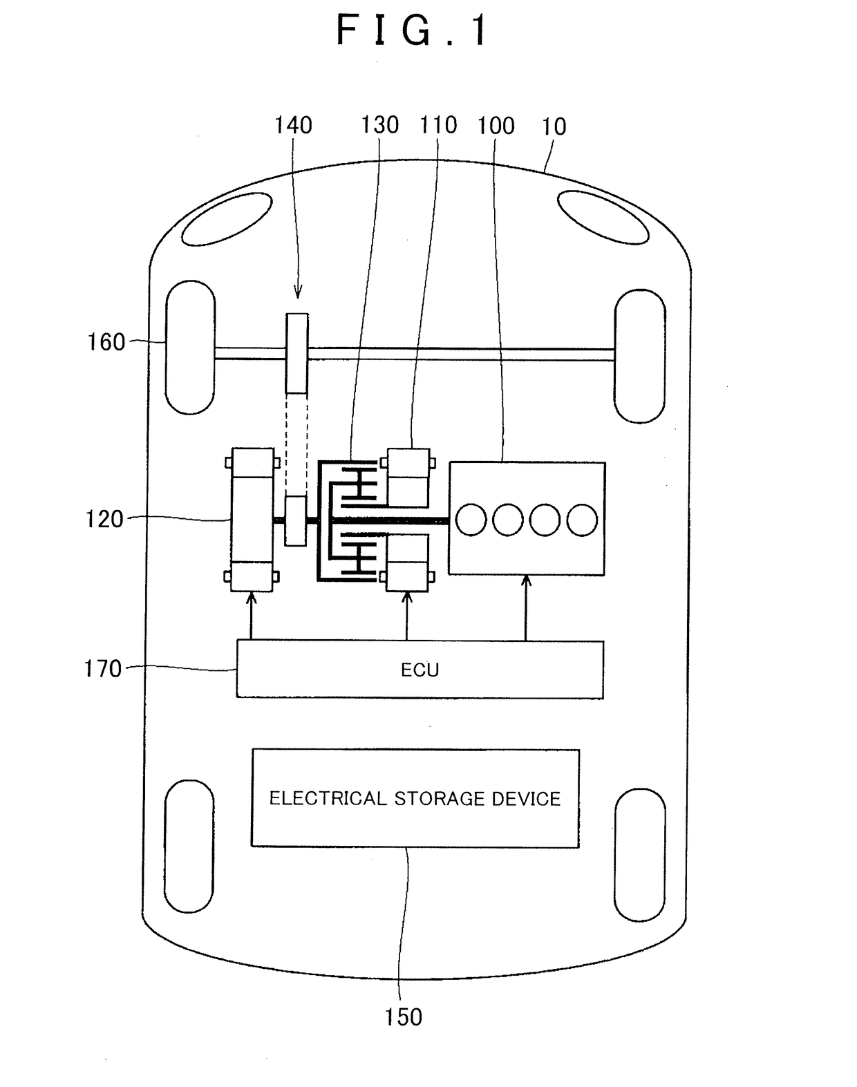
[0040]First, the configuration of an externally chargeable vehicle will be described. FIG. 1 is an overall block diagram of a hybrid vehicle that is shown as an example of the vehicle according to the embodiment of the invention. In the following description, the hybrid vehicle may be simply referred to as “vehicle”. In addition, the hybrid vehicle is illustrative. The invention is also applicable to an electric vehicle, a fuel-cell vehicle, and the like, as long as an electrical storage device is mounted on the vehicle and the vehicle is configured to be chargeable from a device outside the vehicle.
[0041]As shown in FIG. 1, the hybrid vehicle 10 includes an engine 100, a motor generator (MG) 110, an MG 120, a power split mechanism 130, a speed reduction gear 140, an electrical storage device 150, drive wheels 160 and an electronic control unit (ECU) 170.
[0042]The engine 100, the MG 110 and the MG 120 are coupled to the power split mechanism 130. The hybrid vehicle 10 travels on dr...
second embodiment
[0121]However, it is presumable that, depending on the user, a frequency at which timer charging is carried out is low. In the second embodiment, the case where the charging system is designed or set so as not to carry out timer charging even when the time of the timer is set unless otherwise specified and so as to carry out timer charging only when operation to enable the timer is performed will be described. In such a case, a switch for enabling the timer (hereinafter, referred to as timer determination switch) is required instead of the timer cancellation switch.
[0122]The configurations shown in FIG. 1 to FIG. 5 are also the same in the second embodiment. However, the way of usage of the switch 177 regarding timer setting is different.
[0123]FIG. 12 is a flowchart for illustrating control for switching between the enabled and disabled states of the timer according to the second embodiment. This process is a process in the case where autolock is set. As shown in FIG. 12, initially,...
PUM
 Abstract
Description
Claims
Application Information