
Illumination for the detection of raindrops on a window by means of a camera

Active Publication Date: 2017-08-01
CONTI TEMIC MICROELECTRONIC GMBH
View PDF20 Cites 0 Cited by
  • Summary
  • Abstract
  • Description
  • Claims
  • Application Information

AI Technical Summary

Benefits of technology

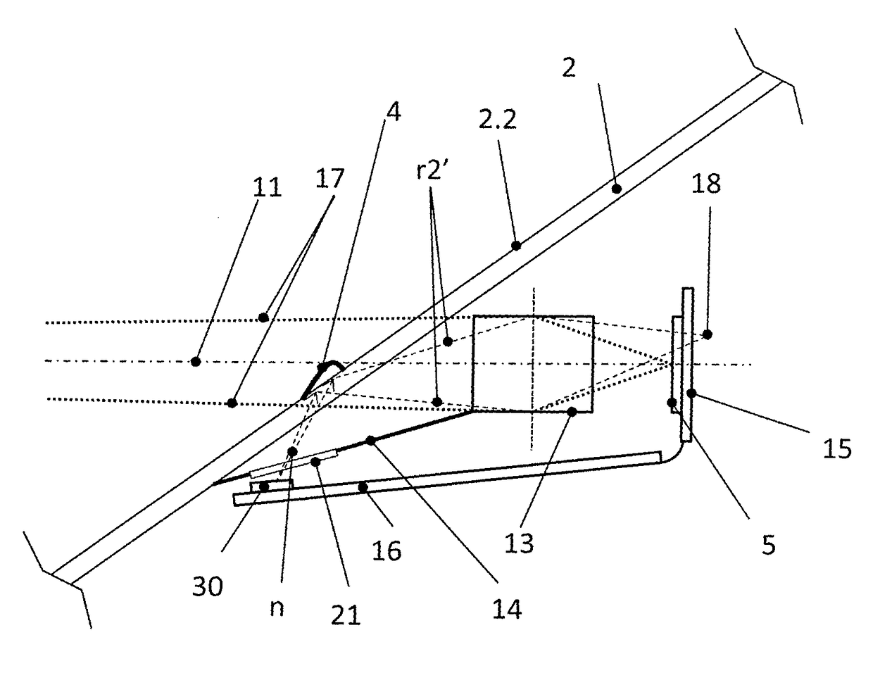
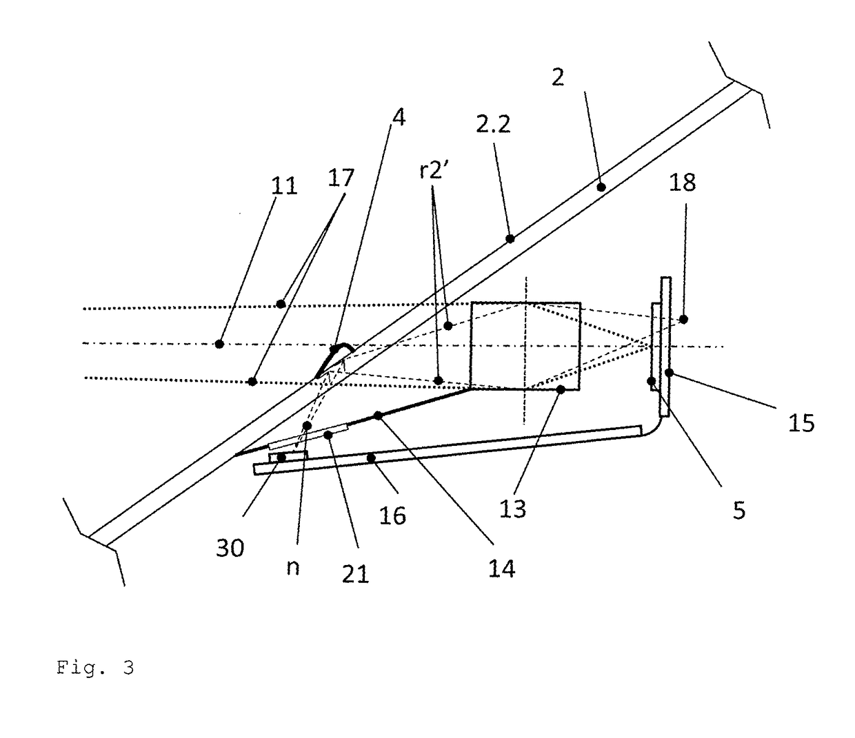
The patent describes a device called a shutter that is placed between a lighting source and a window. This device reduces or prevents the light from spreading in a certain direction (both sideways in this case). The shutter is designed to have a periodical change in the distance between its structures or the width of its individual structures. This causes a spatial modulation of the lighting.

Problems solved by technology

Other road users, e.g. pedestrians, located at the side of a vehicle at the level of the windshield, may be irritated by this.

Method used


Image

  • Illumination for the detection of raindrops on a window by means of a camera
  • Illumination for the detection of raindrops on a window by means of a camera
  • Illumination for the detection of raindrops on a window by means of a camera

Examples


Embodiment Construction

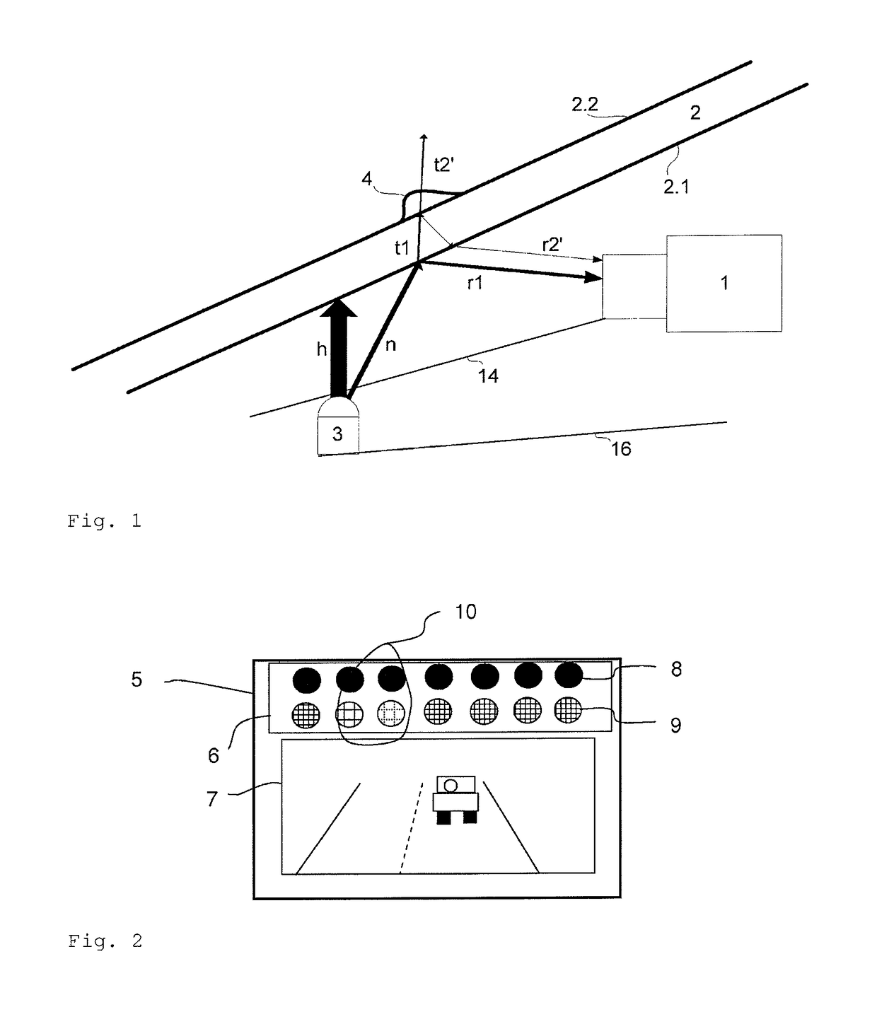
[0034]FIG. 1 shows a longitudinal section of a camera (1) focused on the remote region and a lighting source (3) which emits light (h, n) in the visible wavelength range onto a window (2). The beam paths (h, n, t1, r1, t2′, r2′) explained below are shown schematically. No reflex from the lighting main beam (h) reaches the camera (1). The aperture angle of the lighting is so large that beams reflected from a secondary beam (n) on the inner face (2.1) and outer face (2.2) of the window impinge on the lens or the camera (1) as two spatially separated beams (r1, r2′). Due to the focusing on the remote region, the boundary of the beam bundle is only shown as a blurred image on the image chip (5). Both beams (r1, r2′) are sufficiently separated and their respective light reflexes can be measured with the image sensor (5).

[0035]The portion (r1) of the secondary beam (n) reflected at the air-window interface (or inner face of the window (2.1)) can serve as a reference beam. Of the portion w...


PUM

PropertyMeasurementUnit
distanceaaaaaaaaaa
distanceaaaaaaaaaa
structuresaaaaaaaaaa

Abstract

A device for detecting rain includes a camera and a lighting source for emitting visible light onto a window. The camera and the lighting source are configured and arranged in such a way that the camera can detect a signal of the visible light which the lighting source emits onto the window. The signal which is detected by the camera correlates with visible light of the lighting source, which visible light is reflected or scattered at the inner face of the window or outer face of the window and / or at the raindrop. The visible light passes through a shutter device which causes the light to be blocked or highly attenuated in a predefined direction perpendicular to the illumination direction of structures of the shutter device. In contrast, the light in the direction perpendicular to the predefined direction and to the illumination direction can propagate virtually unimpeded through the shutter device.

Description

CROSS REFERENCE TO RELATED APPLICATIONS[0001]This application is the U.S. National Phase Application of PCT International Application No. PCT / DE2013 / 200377, filed Dec. 19, 2013, which claims priority to German Patent Application No. 10 2013 100 292.7, filed Jan. 11, 2013, the contents of such applications being incorporated by reference herein.FIELD OF THE INVENTION[0002]The invention relates to a device for detecting rain on a window by means of a lighting source and a camera.BACKGROUND OF THE INVENTION[0003]In U.S. Pat. No. 7,259,367 B2, which is incorporated by reference, rain sensing by means of a camera is proposed, said rain sensing providing extensive lighting of the passing-through window of the camera aperture angle with the pane by means of an infrared diode. The camera focus is set to almost infinite and can thus be simultaneously used for driver assistance applications. Due to the imaging on the remote range raindrops are only noticeable as disturbances in the image, whi...

Claims


Application Information

Patent Timeline
Patent Type & Authority Patents(United States)
IPC IPC(8): G01W1/14G01N21/43G01N21/17B60S1/08
CPCG01W1/14G01N21/17G01N21/43B60S1/0844G01N2021/435G01N21/255
Inventor KROKEL, DIETERFEY, WOLFGANGRANDLER, MARTIN
Owner CONTI TEMIC MICROELECTRONIC GMBH
Learn More