Flying user interface

a user interface and flying technology, applied in the field of flying user interfaces, can solve the problems of continuous noise during the flight, difficult to project the path on the road, and not fully mobile,

a user interface and flying technology, applied in the field of flying user interfaces, can solve the problems of continuous noise during the flight, difficult to project the path on the road, and not fully mobile,

US9720519B2Active Publication Date: 2017-08-01VERMA PRAMOD KUMAR

Image

  • Flying user interface
  • Flying user interface
  • Flying user interface

Examples


Embodiment Construction

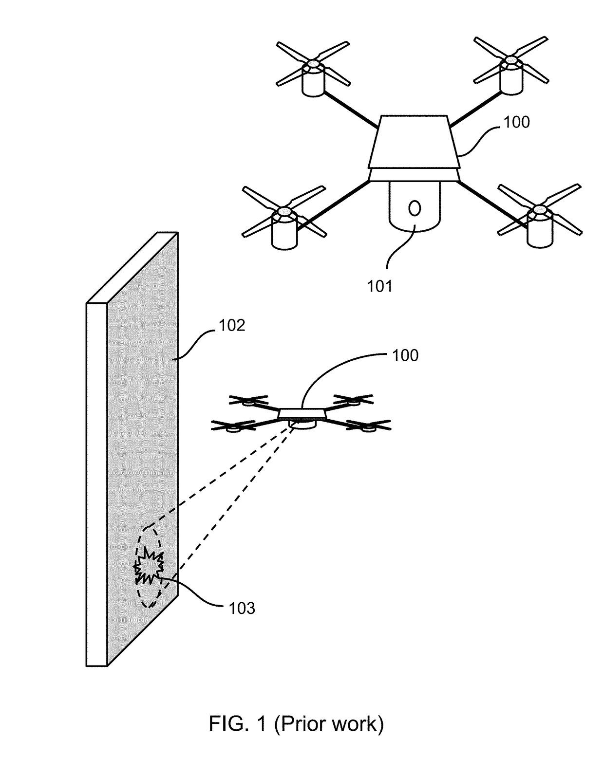
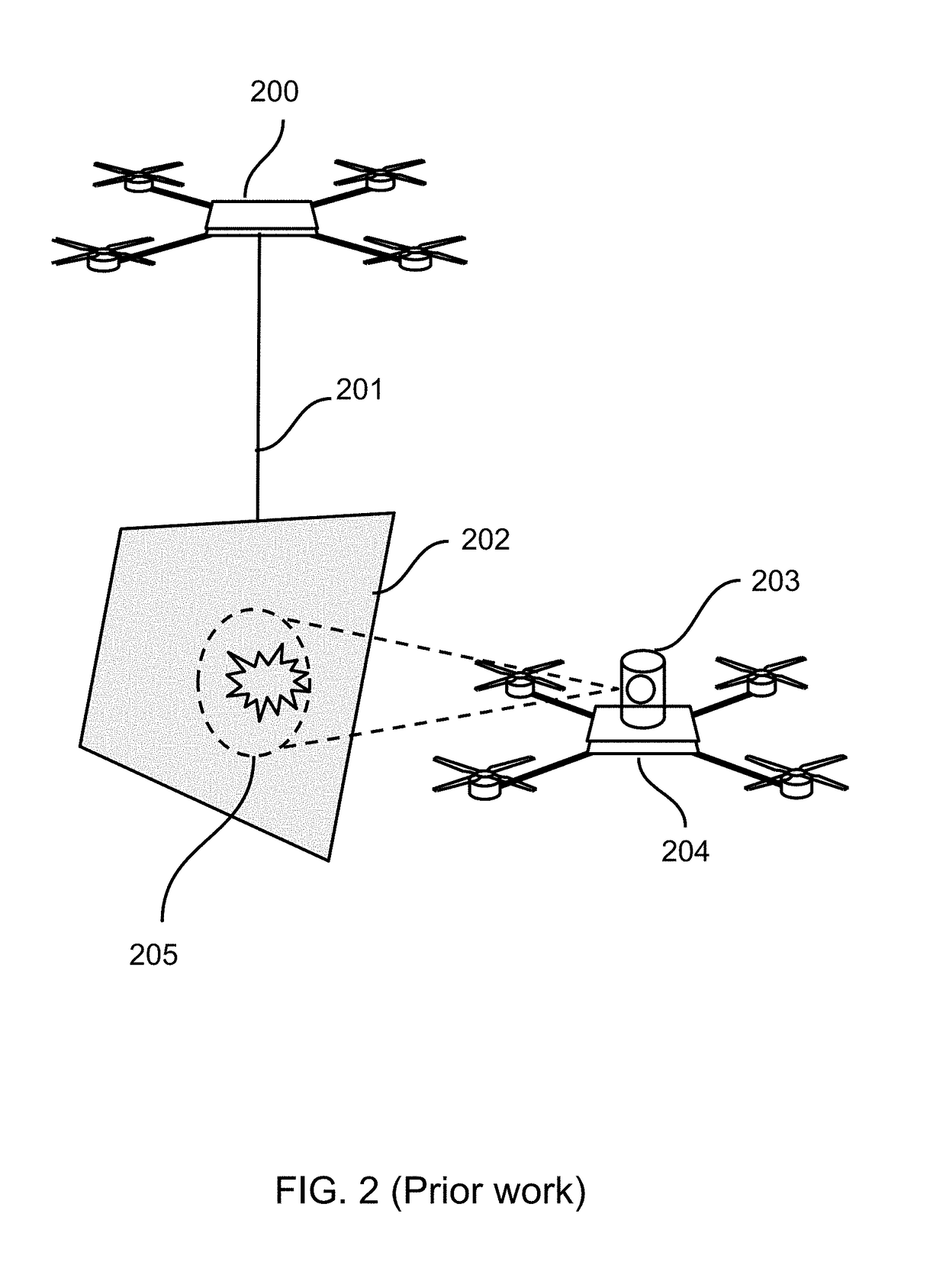
[0094]The main unique feature of this device is its ability to fly, stick, and project user-interface to any nearby surface. Various prior works show how all these individual features or parts were implemented for various applications. One related prior work called “Displaydrone” as shown in FIG. 1 consists of a projector 101 equipped with a drone 100 to display information 103 on surface 102. Similar prior work, as shown in FIG. 2 consists of two drones and a surface. Drone 200 holds the surface in the mid-air using an attachment or rod 201 and drone 204 augments information 205 on a flying display surface 202 using a projector 203. Some prior work such as “SixthSense” consists of a wearable mobile projector camera system 301 as shown in FIG. 3. User 300 can use gesture using hands, body parts, fingers, or markers 302 to interact with the device. FIG. 4 shows how robotic arm 401 called “LUMINAR” can be used to project augmented user interface 403 on a table using projector camera s...


PUM


Abstract

This invention describes a special type of drone called “Flying User Interface” device comprised of a robotic projector-camera system, an onboard digital computer connected with Internet, sensors, and a hardware interface to stick to any surface such as wall, ceilings, etc. Computer further consists of other subsystems, devices, and sensors such as accelerometer, compass, gyroscope, flashlight, etc. Drone flies from one places to another, detects a surface, and sticks to it. After successful sticking mechanism, device stops all its rotators and projects or augments images, information, and user interfaces on the near by surfaces. User interface may contain applications, information about object being augmented and information from Internet. User can interact with user-interface using command and gestures such as hand, body, feet, voice, etc.

Description

CROSS-REFERENCE TO RELATED APPLICATIONS[0001]Not ApplicableSTATEMENT REGARDING FEDERALLY SPONSORED RESEARCH OR DEVELOPMENT[0002]Not ApplicableREFERENCE TO SEQUENCE LISTING, A TABLE, OR A COMPUTER PROGRAM LISTING COMPACT DISK APPENDIX[0003]Not ApplicableBACKGROUND OF THE INVENTION[0004]Field of the Invention[0005]Flying or Mobile User-Interface, Human-Computer Interaction, Human-Robot Interaction, Human-Machine Interaction, Computer-Supported Cooperative Work, Computer Graphics, Robotics, Computer Vision, Artificial intelligence, Personnel Agents or Robots. Object Augmentation, Augmented Reality, Projector Camera System, Gesture Interface, Natural User-Interface, and Drones (Unmanned Aerial Vehicles).[0006]Description of the Related Art[0007]Mobile projector camera systems have various augmented reality applications. Due to their mobility, they support various projector camera system applications of all types and nature. In the context of this invention, we will review few mobile pro...

Claims


Application Information

Patent Timeline
01 Aug 2017
Publication
US9720519B2
IPC
B64C39/02; B62D57/00; G06F3/03; G06F3/01; B25J9/06; G05B15/00
CPC
G06F3/0304; G06F3/017
Inventors
VERMA, PRAMOD KUMAR