Medical manipulator system

a technology of manipulators and actuators, applied in the field of manipulators, can solve problems such as the inability to energize actuators

Active Publication Date: 2017-08-15
KARL STORZ GMBH & CO KG
View PDF49 Cites 794 Cited by
  • Summary
  • Abstract
  • Description
  • Claims
  • Application Information

AI Technical Summary

Benefits of technology

[0013]During one surgical case, the manipulator system increments the usage count of the working unit each time that the usage time thereof exceeds the first preset time. Consequently, the working unit is prevented from being used infinitely and hence from suffering from a durability problem.
[0015]Therefore, since the time for which the working unit can be used is extended only for a final usage event of the working unit, the working unit is prevented from becoming disabled while in use during the final usage event, and hence a surgical operation can be performed smoothly in the surgical case.
[0023]The controller determines whether the surgical case has been switched to another surgical case or not based on whether restarting of the controller is completed within the third preset time from start of the power-off state. If the power switch of the controller is inadvertently turned off, or if the power cable is inadvertently disconnected from the controller, then the controller can determine whether the surgical case has been switched to another surgical case or whether the controller has inadvertently been turned off, by setting the third preset time so as to correspond to a maximum time that is expected to be required to restart the controller. As a result, the controller can appropriately increment the usage count of the working unit.
[0025]Accordingly, when an nth operating unit, where “n” is α greater than the number N of connection ports, is immediately connected to the controller while the controller remains energized, the controller is prevented from failing to recognize that the surgical case has actually been switched to a next surgical case. Therefore, the usage count of the working unit can be incremented appropriately.

Problems solved by technology

Therefore, even if the operator of the manipulator system operates the operation input unit, the actuator cannot be energized.

Method used


Image

  • Medical manipulator system
  • Medical manipulator system
  • Medical manipulator system

Examples


Embodiment Construction

[0044]A medical manipulator system (hereinafter referred to as “manipulator system”) according to a preferred embodiment of the present invention will be described below with reference to the accompanying drawings. Like or corresponding parts are denoted by like or corresponding reference characters throughout the views.

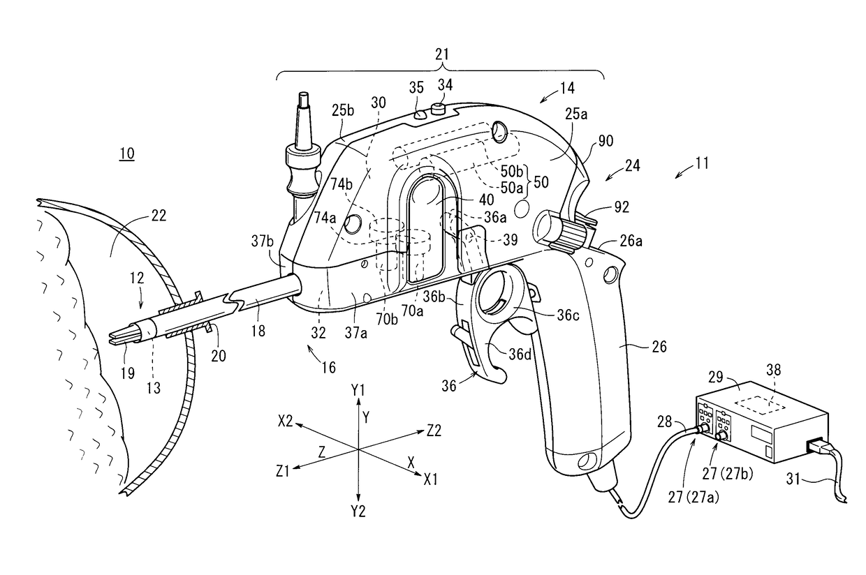
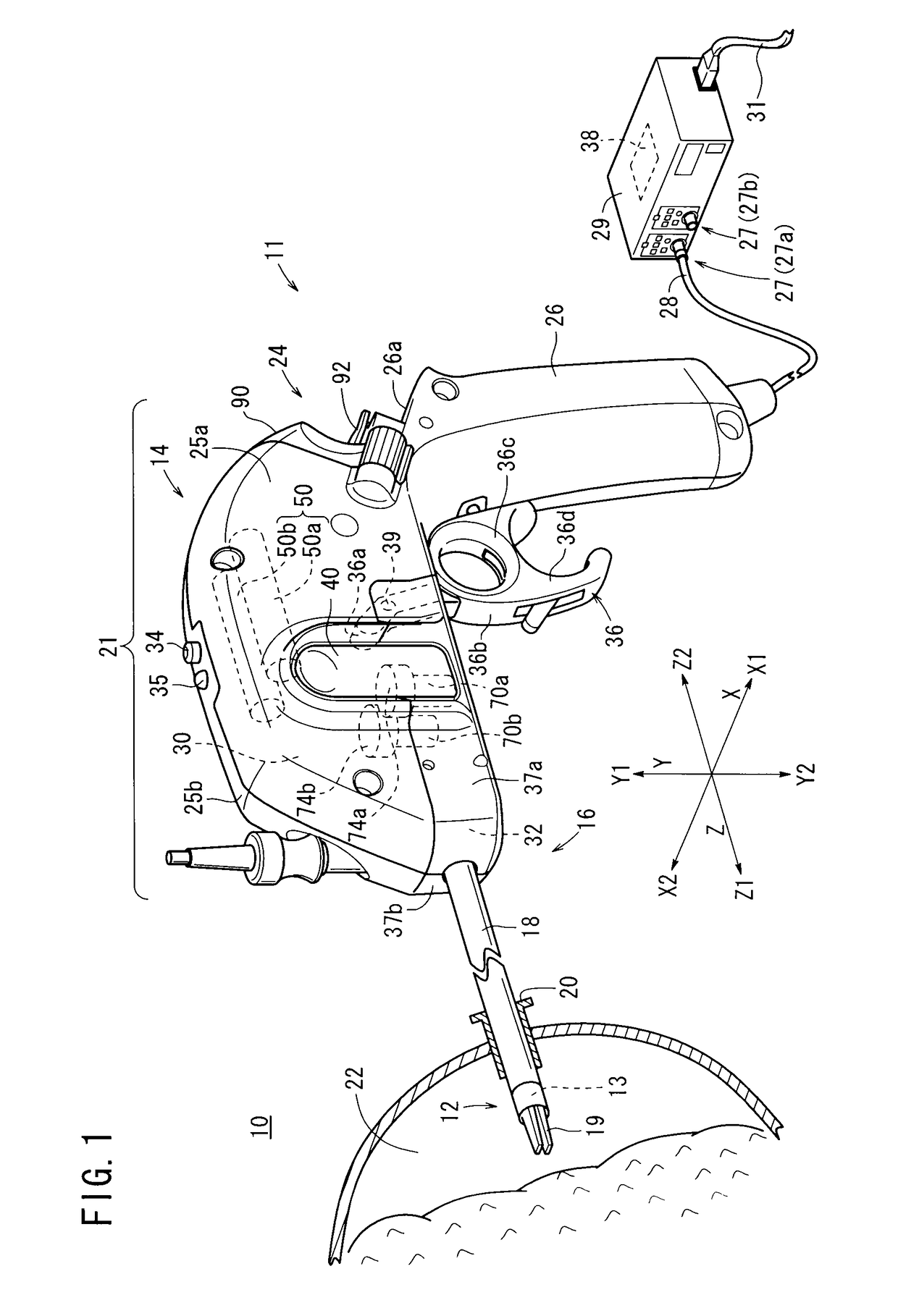
[0045]First, an overall arrangement of a manipulator system 10 according to an embodiment of the present invention will be described below with reference to FIG. 1. As shown in FIG. 1, the manipulator system 10 comprises a manipulator 11 that serves as a medical instrument, which is typically used by a surgeon (operator) for gripping or touching a portion of a living body with a distal-end working unit 12 on the distal end in order to perform a certain treatment. The manipulator system 10 further includes a controller 29 electrically connected to the manipulator 11 by a cable 28. The manipulator 11 includes a body 21, a shaft 18 extending from the body 21, and the di...


PUM


Abstract

A medical manipulator system has an operating unit including a grip handle and a composite input unit, a working unit detachably mounted on the operating unit and including an end effector, and a controller for controlling the operating unit. The controller judges starting and ending of a surgical case and increments the usage count of the working unit based on a manner in which the working unit is mounted and dismounted, and the times at which the working unit is mounted and dismounted, and disables the working unit if the usage count of the working unit exceeds a preset count.

Description

BACKGROUND OF THE INVENTION[0001]Field of the Invention[0002]The present invention relates to a medical manipulator system having an operating unit with an input member operable to enter input actions, and a working unit having an end effector such as a gripper or the like mounted on the distal end of a shaft, the working unit being detachably mounted on the operating unit.[0003]Description of the Related Art[0004]According to endoscopic surgery (also called laparoscopic surgery), it is customary to form a plurality of holes or incisions in the abdominal region of a patient, insert trocars (tubular instruments) into the respective incisions, and introduce a laparoscope and a plurality of pairs of forceps through the trocars into the body cavity. End effectors such as a gripper for gripping a living tissue, scissors, a blade of an electrical scalpel, etc., are mounted on distal ends of the forceps. After the laparoscope and the forceps have been inserted into the body cavity, a surge...

Claims


Application Information

Patent Timeline
Patent Type & Authority Patents(United States)
IPC IPC(8): A61B17/00A61B34/00A61B90/96A61B17/29A61B90/98A61B90/00
CPCA61B17/29A61B34/70A61B90/96A61B90/98A61B2017/00128A61B2017/00132A61B2017/00199A61B2017/00398A61B2017/00473A61B2090/0803A61B2090/0805A61B2090/0814
Inventor KATSUKI, RYOHEIJINNO, MAKOTOOMORI, SHIGERUHITOTSUYANAGI, MASAOMARLOTTE, JACKHIRZEL, DEANNASHIMOYAMA, PARINAKAMURA, RIE
Owner KARL STORZ GMBH & CO KG
Why Eureka
Try Eureka