
Desktop three-dimensional scanner for dental use provided with two-axis motion unit in which camera and projector are coupled to unit for changing horizontal axis of rotation of stage

a three-dimensional scanner and dental technology, applied in the field of three-dimensional scanners, three-dimensional measurement, cad/cams, can solve the problems of high cost, inability to fix the target object by such additional fixing means or fixing jigs, etc., and achieve the effect of reducing costs and high cos

Active Publication Date: 2017-08-22
DOF
View PDF13 Cites 5 Cited by
  • Summary
  • Abstract
  • Description
  • Claims
  • Application Information

AI Technical Summary

Benefits of technology

Enables cost-effective scanning of variously shaped dental prostheses without the need for multiple fixing jigs, improving scanning efficiency and reducing costs by maintaining object stability during the scanning process.

Problems solved by technology

However, when a target object to be scanned is dental prostheses, the target object cannot be fixed by such additional fixing means or fixing jig due to their various shapes.
However, the plurality of fixing jigs for precise scanning may cause high costs, because they should have accuracy.

Method used


Image

  • Desktop three-dimensional scanner for dental use provided with two-axis motion unit in which camera and projector are coupled to unit for changing horizontal axis of rotation of stage
  • Desktop three-dimensional scanner for dental use provided with two-axis motion unit in which camera and projector are coupled to unit for changing horizontal axis of rotation of stage
  • Desktop three-dimensional scanner for dental use provided with two-axis motion unit in which camera and projector are coupled to unit for changing horizontal axis of rotation of stage

Examples


Embodiment Construction

[0011]Preferred embodiments of the present invention will be described below in detail with reference to the accompanying drawings where the same components are provided with the same reference numerals even if they are shown in different figures. In describing the present invention, if a detailed explanation for a related known function or construction is considered to unnecessarily divert the gist of the present invention, such explanation has been omitted but would be understood by those skilled in the art.

[0012]A three-dimensional (3D) scanner is a device used to collect numerical data with respect to a shape of a target object, and to implement a digital 3D model through the collected numerical data. There are a plurality of technical methods to implement such 3D scanner, and each technique method has advantages and disadvantages in the aspect of technique and cost. In the field of dentistry, widely used are desktop three-dimensional scanners having a size large enough for dent...


PUM


Abstract

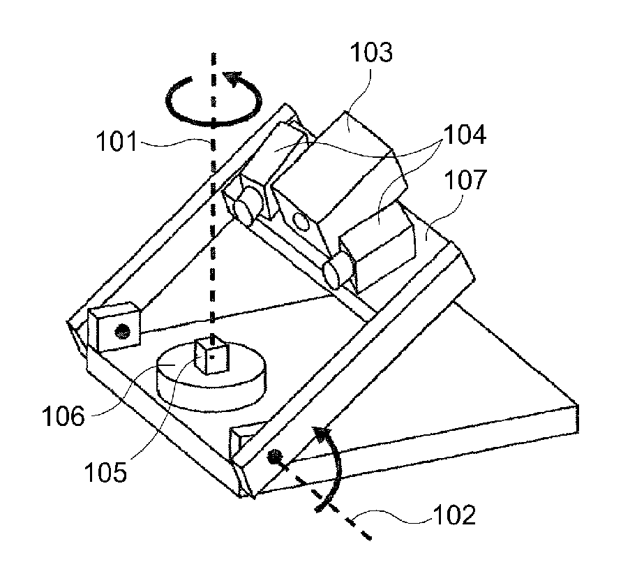
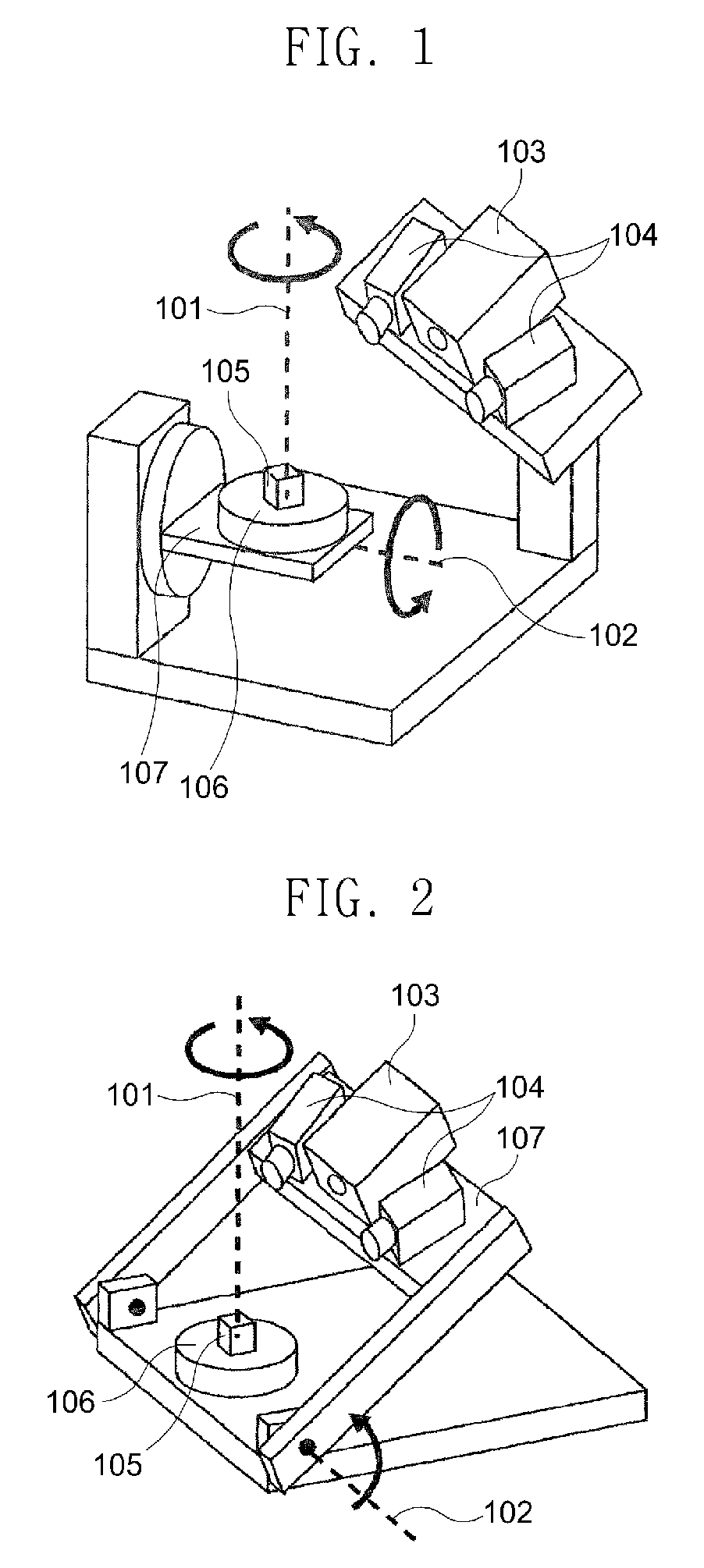
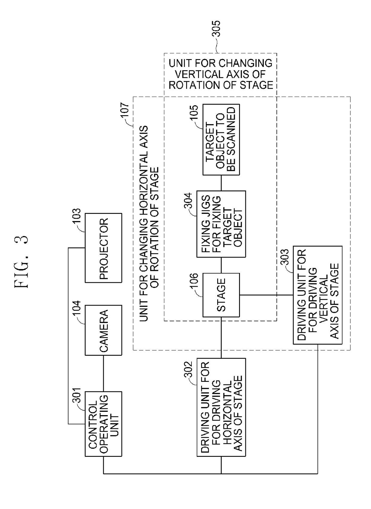
In a desktop three-dimensional scanner for dental use of the related art, a two-axis rotation motion unit, on which a target object can be placed and rotated in order to image the entire shape of the target object, is coupled to the scanner, and thus, when a subject is placed on the imaging stage and is rotated along the horizontal axis of rotation of the stage, the subject is dropped from the stage by gravity after being inclined, and accordingly, additional fixing means or a receiving jig should be placed on the stage together with the subject to prevent same. In such a case, inconvenience is caused because the target objects to be scanned have various shapes and the fixing means or receiving jigs should fit the shapes thereof. According to one embodiment of the desktop three-dimensional scanner for dental user of the present invention, a camera and a projector are provided on the unit for changing the horizontal axis of rotation of the imaging stage, and thus a target object does not have to be inclined during the scanning process and dental prostheses of various shapes can be three-dimensionally scanned even without additional fixing means or a receiving jig.

Description

TECHNICAL FIELD[0001]The present invention relates to a three-dimensional scanner, three-dimensional measurement, and CAD / CAM.BACKGROUND ART[0002]A three-dimensional (3D) scanner is a device used to collect numerical data with respect to a shape of a target object. The collected numerical data may be used to implement a digital 3D model. There are a plurality of technical methods to implement such 3D scanner, and each technique method has advantages and disadvantages in the aspect of technique and cost. In case of a desktop three-dimensional scanner for dental use configured to scan a target object having a comparatively small size, such as a dental replica, an optical method is usually used, and products coupled to a two-axis motion unit for scanning an entire shape of a target object, are widely used. The present invention is related to a method capable of effectively implementing a two-axis motion unit of a desktop three-dimensional scanner for dental use.[0003]In a desktop three...

Claims


Application Information

Patent Timeline
Patent Type & Authority Patents(United States)
IPC IPC(8): H04N13/02G01B11/24A61C9/00
CPCA61C9/006G01B11/24H04N13/0275H04N13/275G01B5/0004G01B2210/54G01B11/2545A61C19/04
Inventor LEE, YOUNGJONG
Owner DOF
Learn More