Systems and methods for improved water rotors

Active Publication Date: 2017-08-22
WATEROTOR ENERGY TECH
View PDF2 Cites 1 Cited by
  • Summary
  • Abstract
  • Description
  • Claims
  • Application Information

AI Technical Summary

Problems solved by technology

Many conventional renewable recourse energy generation technologies, however, require large amounts of capital and/or real estate to implement.
With respect to water generation facilities, for example, typical water rotors may be expensive to build and/or may be required to be sited in fast moving water.
A typical Savonius styled water roto

Method used


Image

  • Systems and methods for improved water rotors
  • Systems and methods for improved water rotors
  • Systems and methods for improved water rotors

Examples


Example

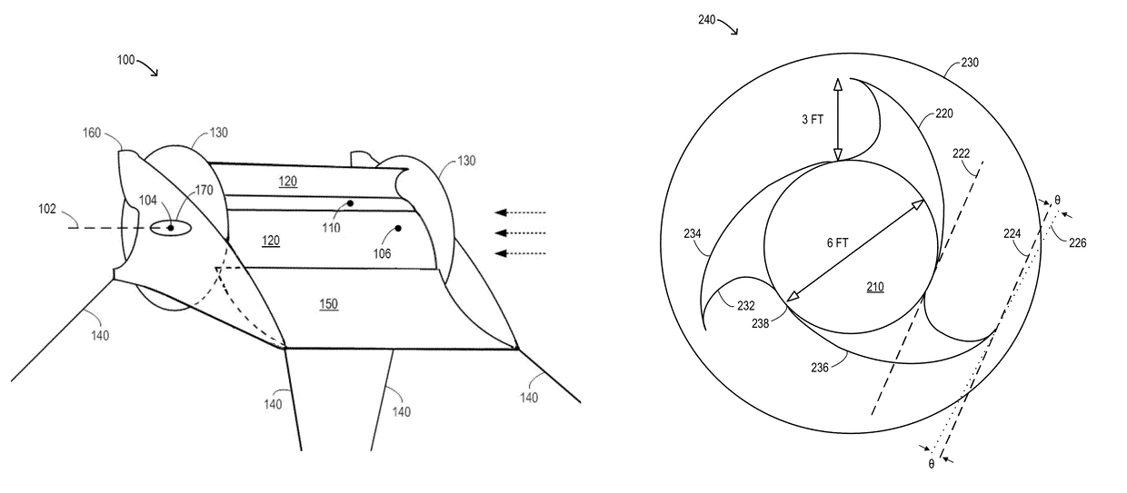
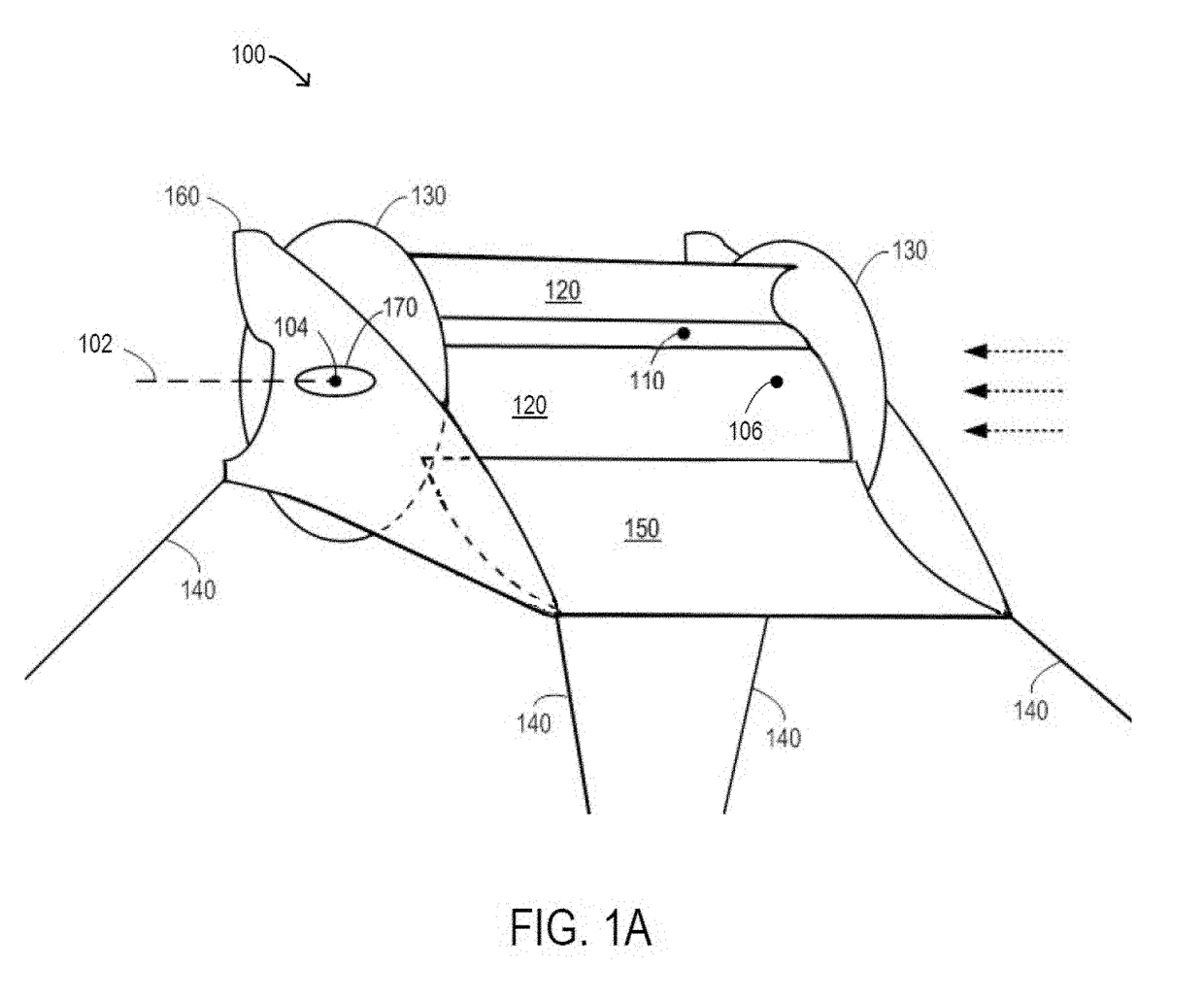
[0018]According to some embodiments, systems and methods for tethered water rotors and / or turbines are provided. Tethered water turbines that rotate about a horizontal axis in response to a normal water force may, for example, be utilized to produce electrical energy. In some embodiments, the tethered water turbines are may be at least slightly buoyant. According to some embodiments, the turbines are held more perpendicular will less lean, at least in part, by the Magnus or Savonius effect and / or other lifting effects. Such turbines may, for example, be relatively inexpensive, easily deployable and / or manageable, and / or may otherwise provide advantages over previous systems. According to some embodiments, small tethered water turbines are deployed in emergency, as-needed, and / or mobile applications. In some embodiments, much larger turbines (e.g., hundreds of meters in length, or more) may be deployed. Some embodiments may provide an ability to capture water flowing energy in low sp...


PUM


Abstract

According to some embodiments, a drum may be submerged in water and extend horizontally along a center axis between a first point on a first side of the drum and a second point on a second side of the drum opposite the first side. Three curved vanes may be attached to the drum such that the vanes, when acted upon by a water flow perpendicular to the axis, are operable to cause rotation about the axis, wherein an edge portion of each vane, located substantially opposite the drum, defines a plane substantially parallel to a plane defined by a surface of the drum located between the edge portion and the axis. An electrical generator coupled to the drum may convert rotational energy produced by the rotation about the axis into electrical energy.

Description

CROSS-REFERENCE TO RELATED APPLICATIONS[0001]The present application is a continuation of U.S. patent application Ser. No. 13 / 236,955 entitled “SYSTEMS AND METHODS TO GENERATE ELECTRICITY USING A THREE VANE WATER TURBINE” and filed Sep. 20, 2011. The entire contents of that application is incorporated herein by reference.TECHNICAL FIELD[0002]The present disclosure relates generally to systems and methods for providing electrical energy generation via water power, and more particularly to systems and methods for improved water rotors and / or turbines.BACKGROUND[0003]The use of renewable energy resources continues to be an important factor in satisfying energy demands while substantially reducing environmental impacts. Solar, hydropower, and water resource technologies, for example, continue to decrease in cost and increase in efficiency, while practically eliminating adverse environmental effects. Many conventional renewable recourse energy generation technologies, however, require la...

Claims


Application Information

Patent Timeline
IPC IPC(8): F03B13/10H02K7/18F03B17/06F03B7/00
CPCF03B7/003H02K7/1823F03B17/063F05B2220/706F05B2240/301Y02E10/20Y02E10/30
Inventor FERGUSON, FREDERICK D.
Owner WATEROTOR ENERGY TECH
Why Eureka
Try Eureka