Clamping apparatus for portable electronic device

a portable electronic device and apparatus technology, applied in electrical apparatus, substation equipment, telephone set construction, etc., can solve the problems of inconvenience to the user of the mobile phone with a compact size, inconvenience for those persons, etc., and achieve the effect of convenient placement of the portable electronic devi

Active Publication Date: 2017-08-29
FAN EAGLE
View PDF8 Cites 23 Cited by
  • Summary
  • Abstract
  • Description
  • Claims
  • Application Information

AI Technical Summary

Benefits of technology

[0007]A primary objective of the present invention is to provide a clamping apparatus including novel interior structures to permit easy placing of a portable electronic device thereon or releasing of the electronic device therefrom. Placing of the portable electronic device on the clamping apparatus activates a unidirectional restriction unit, which in turn, permits movement of two clamping units toward each other, thereby clamping the electronic device tightly therebetween. To release the electronic device, a manipulating unit is activated, which in turn, permits movement of two clamping units away from each other, thereby permitting removal of the electronic device from the clamping apparatus of the present invention.
[0008]Another objective of the present invention is to provide a clamping apparatus including a manipulating unit, activation of the same each time results only a limited movement of the clamping units away from each other, thereby providing convenience to the user in fetching the electronic device without falling off the clamping apparatus of the present invention. In other words, the clamping units are required to move toward each other only within said limited distance next time, when placing the electronic device on the clamping apparatus of the present invention, thereby permitting swift placing of the electronic device on the clamping apparatus.

Problems solved by technology

Therefore, it is inconvenient for those persons whose thumbs and index fingers are not large enough to reach the clamping arms for moving toward each other.
Whenever the clamping arms are spaced apart at the greatest distance, a mobile phone of compact size placed thereon is likely to fall off the apparatus prior to movement of the clamping arms toward each other or away from each other, thereby causing inconvenience to the user of the mobile phone with a compact size.

Method used


Image

  • Clamping apparatus for portable electronic device
  • Clamping apparatus for portable electronic device
  • Clamping apparatus for portable electronic device

Examples


Embodiment Construction

[0023]The accompanying drawings are included to provide a further understanding of the invention, and are incorporated in and constitute a part of this specification. The drawings illustrate embodiments of the invention and, together with the description, serve to explain the principles of the invention.

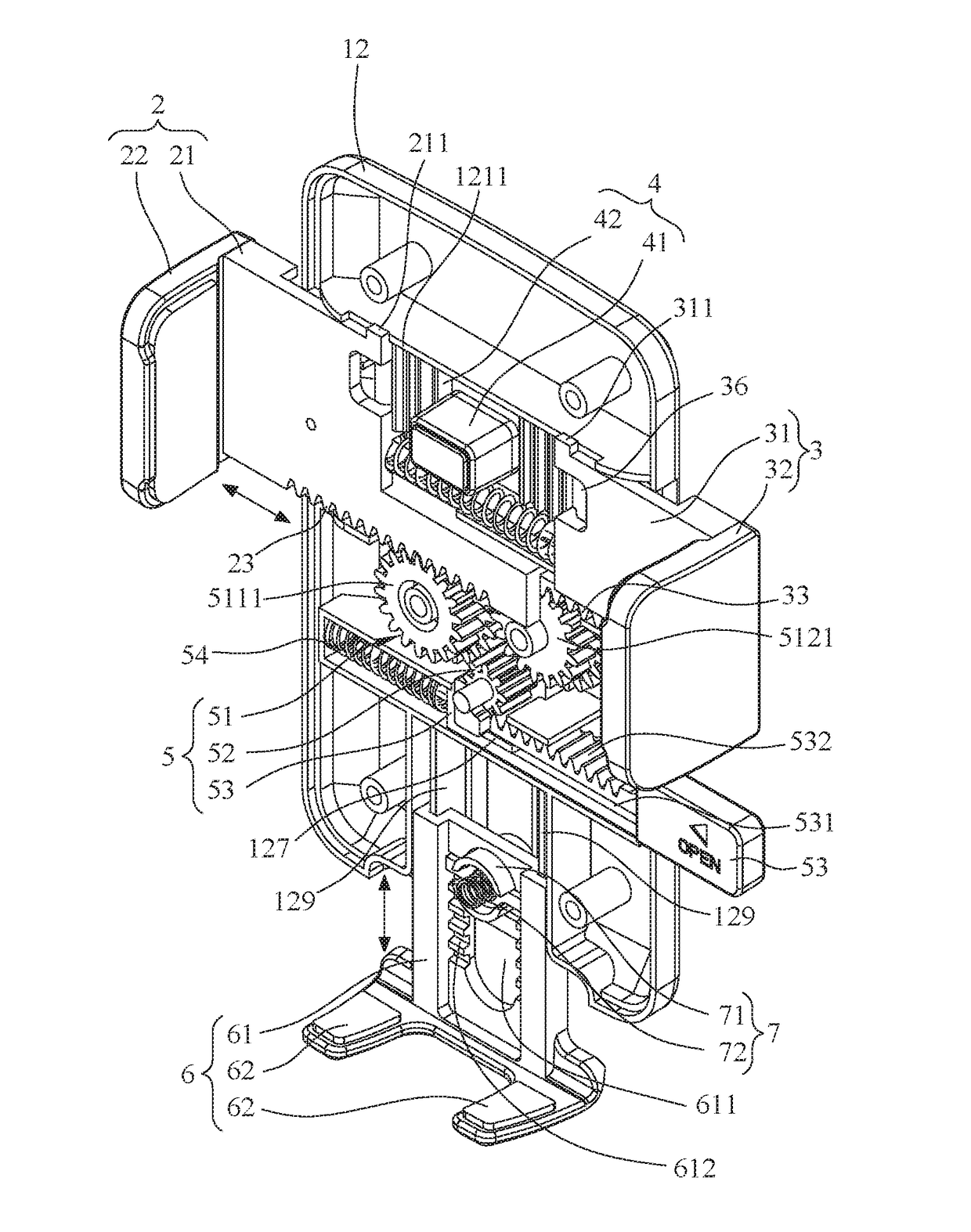
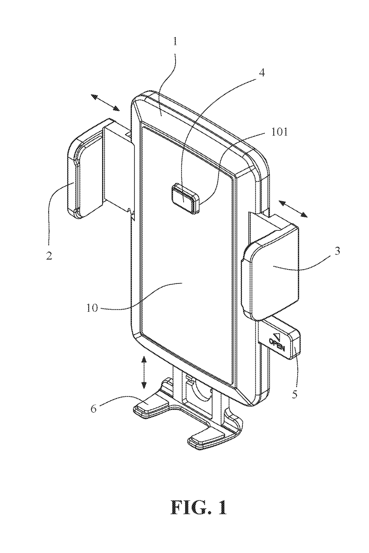
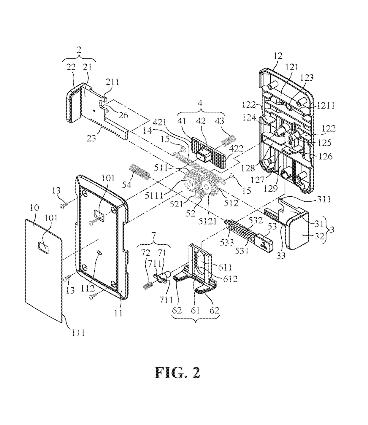
[0024]FIG. 1 is a perspective front view of a clamping apparatus of the present invention for a portable electronic device. As shown, the clamping apparatus of the present invention includes a machine base 1, left and right clamping units 2, 3, a unidirectional restriction unit 4 and a manipulating unit 5. The machine base 1 defines a holding plate 10 that is adapted to receive an electronic device (see FIG. 7A) thereon and that is formed with an opening 101. The left and right clamping units 2, 3 are installed on two opposite sides of the machine base 1 and are movable relative to each other. The unidirectional restriction unit 4 is installed within the base 1, is connected operably...


PUM


Abstract

A clamping apparatus includes: a base defining a holding plate; two clamping units installed on the machine base and movable relative to each other; a unidirectional restriction unit restricting the clamping units from moving toward a center of the holding plate, having a portion exposed to an exterior of the holding plate such that an applied pressure results in withdrawal of the portion into the base and releases the clamping units from moving, thereby permitting the clamping units to move toward each other to clamp an electronic device tightly; and a manipulating unit is disposed in the base and has an manipulating part exposed to an exterior of the base such that activation of the manipulating part results in causing simultaneous movement of the clamping units away from each other and releasing the electronic device from the clamping units.

Description

BACKGROUND OF THE INVENTION[0001]1. Field of the Invention[0002]The present invention relates generally to a clamping apparatus, and more particularly to a clamping apparatus for a portable electronic device, including two clamping units capable of quickly and tightly clamping the portable electronic device once placed thereon and when the clamping force is removed, the two clamping units moves gradually away from each other so as to release the portable electronic from clamping therebetween.[0003]2. The Prior Arts[0004]Portable electronic devices (such as mobile phones, GPS and driving recorders) are prevalent nowadays and are mounted in vehicles, on motorbikes or in offices by means of clamping apparatuses.[0005]A conventional clamping apparatus generally includes a machine base and two clamping arms installed on two opposite sides of the machine base for clamping an electronic device therebetween. Due to different of interior structures so does the movements of the clamping arms ...

Claims


Application Information

Patent Timeline
Patent Type & Authority Patents(United States)
IPC IPC(8): H04M1/00H04M1/04H04B1/3888H04B1/38
CPCH04B1/3888H04M1/04
Inventor FAN, EAGLE
Owner FAN EAGLE
Why Eureka
Try Eureka