Fuel tank

a technology for fuel tanks and tanks, applied in the field of fuel tanks, can solve the problems of large distance between the bracket, the interior of the tank main body is rather dark and difficult to see, and the opening area of the opening of the tank main body is relatively small

Inactive Publication Date: 2017-09-05
AISAN IND CO LTD
View PDF9 Cites 8 Cited by
  • Summary
  • Abstract
  • Description
  • Claims
  • Application Information

AI Technical Summary

Benefits of technology

[0006]In an aspect of this disclosure, a fuel tank includes a tank main body having an opening, a pump unit mounted to a mounting position on a bottom of the tank main body through the opening and having a fuel pump and a pump retaining member retaining the fuel pump, and a guide means configured to guide the pump unit from an opening side of the tank main body to the mounting position on a bottom side of the tank main body. The guide means includes a guide rail provided on the tank main body and a slider provided on the pump unit. The slider is configured to be slidably engaged with the guide rail. In this construction, when mounting the pump unit in the tank main body, the slider is slidably engaged with the guide rail of the guide means, whereby the pump unit is guided from the opening side of the tank main body to the mounting position on the bottom side. Thus, it is possible to properly move the pump unit to the mounting position easily without being at a loss. As a result, it is possible to shorten the operation time. Accordingly, it is possible to achieve an improvement in terms of the mounting property of the pump unit with respect to the tank main body.
[0007]In another aspect of this disclosure, a pair of the guide means are provided on both sides of the pump unit. In this construction, the pump unit is guided by both guide means, so that it is possible to achieve an improvement in terms of the mounting property of the pump unit with respect to the tank main body.

Problems solved by technology

However, the opening area of the opening of the tank main body is relatively small.
Further, the interior of the tank main body is rather dark and hard to see.
Further, the distance from the opening of the tank main body to the bracket is rather large.
Thus, when mounting the pump unit to the bracket by inserting it through the opening of the tank main body, the position of the bracket is rather hard to find.
Thus, the mounting of the pump unit to the tank main body is rather hard to perform.

Method used


Image

  • Fuel tank
  • Fuel tank
  • Fuel tank

Examples


first embodiment

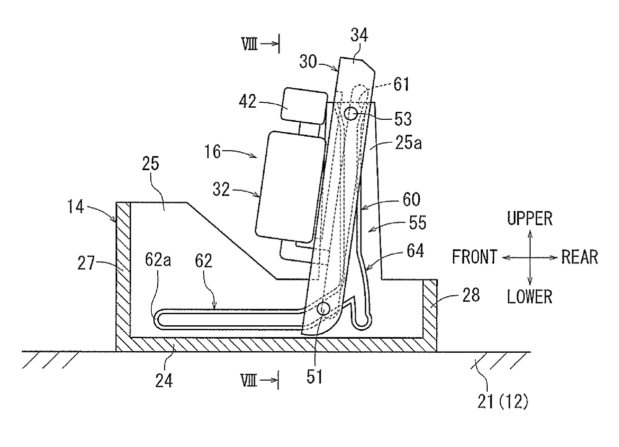
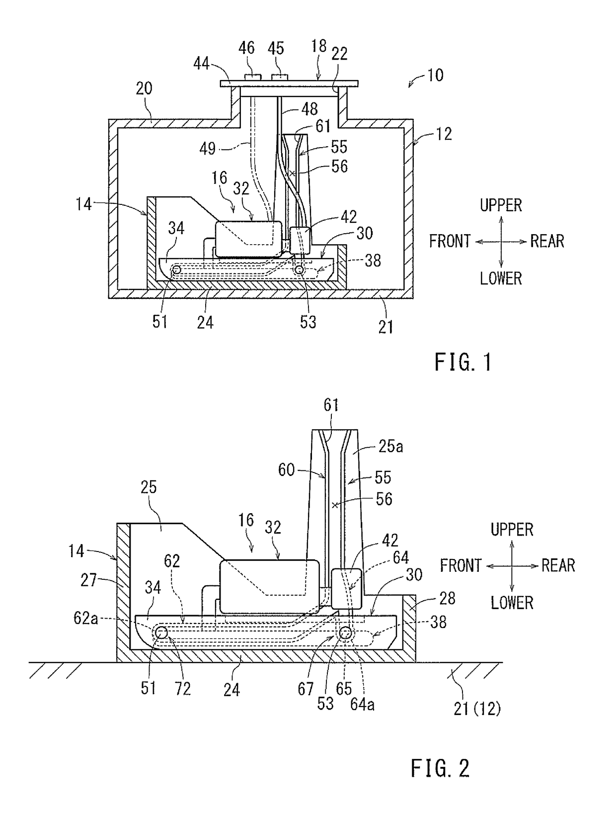
[0054]A fuel tank 10 is configured to store fuel for an internal combustion engine of a vehicle, such as an automobile. As shown in FIG. 1, the fuel tank 10 is equipped with a tank main body 12, a sub tank 14, a pump unit 16, and a flange unit 18. In the drawings, the vertical direction corresponds to the gravitational direction or the so-called top-bottom direction of the fuel tank 10 as mounted in the vehicle. Further, for the sake of convenience, the front-rear direction and the right-left direction of the fuel tank 10 are determined as indicated by the arrows in the drawings. The arrows, however, do not specify the direction in which the fuel tank and the fuel pump are arranged.

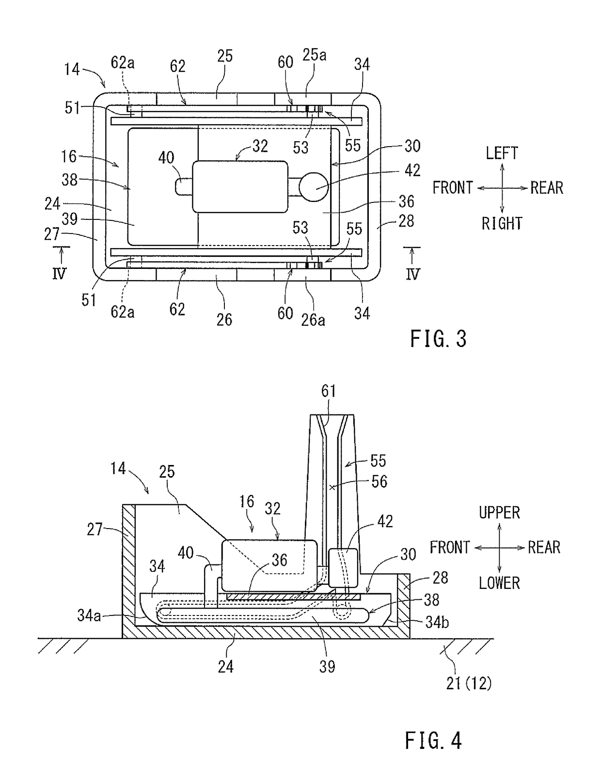
[0055]The tank main body 12 will be described based on FIGS. 2 to 4. The tank main body 12 is formed as a hollow container having an upper surface portion 20 and a bottom surface portion 21. The upper surface portion 20 has a tank hole 22 formed as a round opening. The bottom surface portion 21 is formed...

seventh embodiment

[0111]A seventh embodiment will be described based on FIGS. 21 and 22. As shown in FIG. 21, each front side guide pin 110 of the mount 30 of the pump unit 16 of the present embodiment is formed, for example, in an elongated-round-shaft-like configuration having a cross-section elongated in a direction parallel to the longitudinal direction of the mount 30. Each rear side guide pin 112 of the mount 30 is formed, for example, in a rectangular-shaft-like configuration.

[0112]The guide rails 114 of the present embodiment are provided symmetrically on the bottom plate portion 24 of the sub tank 14 having the same configuration with that of the first embodiment. Because the right and left guide rails 114 symmetrically have the same configurations with each other, a detailed configuration of the left guide rail 114 shown in FIG. 21 will be described, whereas that of the right guide rail 114 will not be described. The left guide rail 114 is formed in a chevron-shaped configuration having a f...

eleventh embodiment

[0147]Further, in the present embodiment, the guide pins 160 and the guide pieces 166 of the eleventh embodiment are changed to front side guide pins 182 and rear side guide pins 184, respectively. The front side guide pins 182 are arranged at the front end portions of both right and left side surfaces of the mount 30. The front side guide pins 182 are formed, for example, as round shafts. The rear side guide pins 184 are arranged at the rear end portions of both right and left side surfaces of the mount 30. The rear side guide pins 184 are formed, for example, as round shafts. Further, the lock pieces 162 as the “tank main body side support portion” and the front side guide pins 182 as the “pump unit side support portion” form rotation support means 186 capable of mutual rotation and detachable engagement as shown in FIGS. 30 through 32. Further, on the step portions 180 of the bottom plate portion 24 of the sub tank 14, engagement grooves 188 are formed between both regulation pie...


PUM


Abstract

A fuel tank includes a tank main body having an opening, a pump unit mounted to a mounting position on a bottom of the tank main body through the opening and having a fuel pump and a pump retaining member retaining the fuel pump and, and a guide means configured to guide the pump unit from an opening side of the tank main body to the mounting position on a bottom side of the tank main body. The guide means includes a guide rail provided on the tank main body and a slider provided on the pump unit. The slider is configured to be slidably engaged with the guide rail.

Description

CROSS-REFERENCE TO RELATED APPLICATIONS[0001]This application claims priority to Japanese patent application serial number 2015-123136, filed Jun. 18, 2015, the contents of which are incorporated herein by reference.STATEMENT REGARDING FEDERALLY SPONSORED RESEARCH OR DEVELOPMENT[0002]Not applicable.BACKGROUND[0003]This disclosure relates to a fuel tank equipped with a tank main body storing fuel for an internal combustion engine, and a pump unit having a fuel pump force-feeding the fuel in the tank main body to the internal combustion engine.[0004]Japanese Laid-Open Patent Publication No. 2003-172217 discloses a conventional fuel tank equipped with a tank main body, a bracket, and a pump unit. The bracket is provided at the bottom portion of the tank main body. The pump unit has a fuel pump and a pump retaining member holding the fuel pump. The pump unit is disposed on the bracket such that the axial direction of the pump unit is oriented horizontally. The tank main body has an open...

Claims


Application Information

Patent Timeline
Patent Type & Authority Patents(United States)
IPC IPC(8): F02M37/04F02M37/00F02M37/22F02M37/02F02M37/10F02M37/34F02M37/50
CPCF02M37/0047F02M37/0076F02M37/103F02M37/106F02M37/025F02M37/10F02M37/22F02M37/50F02M37/34
Inventor IKEYA, MASAKI
Owner AISAN IND CO LTD
Why Eureka
Try Eureka