Motor drive device

a technology of motor drive and drive shaft, which is applied in the direction of electronic commutator control, electronic commutator motor control, commutation monitoring, etc., can solve the problems of improving hardware performance during higher-speed rotation drive etc., to achieve the effect of improving hardware performance, stably driving synchronous motor, and facilitating approximation to target modulation factor waveform

Active Publication Date: 2017-09-05
DENSO CORP
View PDF56 Cites 1 Cited by
  • Summary
  • Abstract
  • Description
  • Claims
  • Application Information

AI Technical Summary

Benefits of technology

[0008]It is an object of the present disclosure to provide a motor drive device that can stably drive the motor without improving hardware performance during higher-speed rotation drive.
[0010]Thus, when the magnification of the sampling frequency with respect to the target modulation factor waveform frequency becomes less than the predetermined value at the time of increasing the motor rotation number in the other modulation scheme, the control device switches the PWM modulation scheme from the other modulation scheme to the three-phase modulation scheme. That is, when the control modulation factor value sampling number in one period from the target modulation factor waveform becomes less than the predetermined value at the time of increasing the rotation number in the other modulation scheme, the control device changes the modulation scheme from the other modulation scheme to the three-phase modulation scheme. Therefore, when the control modulation factor value sampling number in one period decreases so that a control modulation factor waveform formed by sampling values deviates from the target modulation factor waveform, it is possible to adopt the three-phase modulation scheme which facilitates approximation to the target modulation factor waveform, even with a small sampling number. This enables relative stable higher-speed rotation of the motor by switching the modulation scheme from the other modulation scheme to the three-phase modulation scheme without improving hardware performance such as the processing frequency of the control device. Thus, it is possible to stably drive the synchronous motor without improving hardware performance during higher-speed rotation drive.

Problems solved by technology

Thus, it is possible to stably drive the synchronous motor without improving hardware performance during higher-speed rotation drive.

Method used


Image

  • Motor drive device
  • Motor drive device
  • Motor drive device

Examples


first embodiment

[First Embodiment]

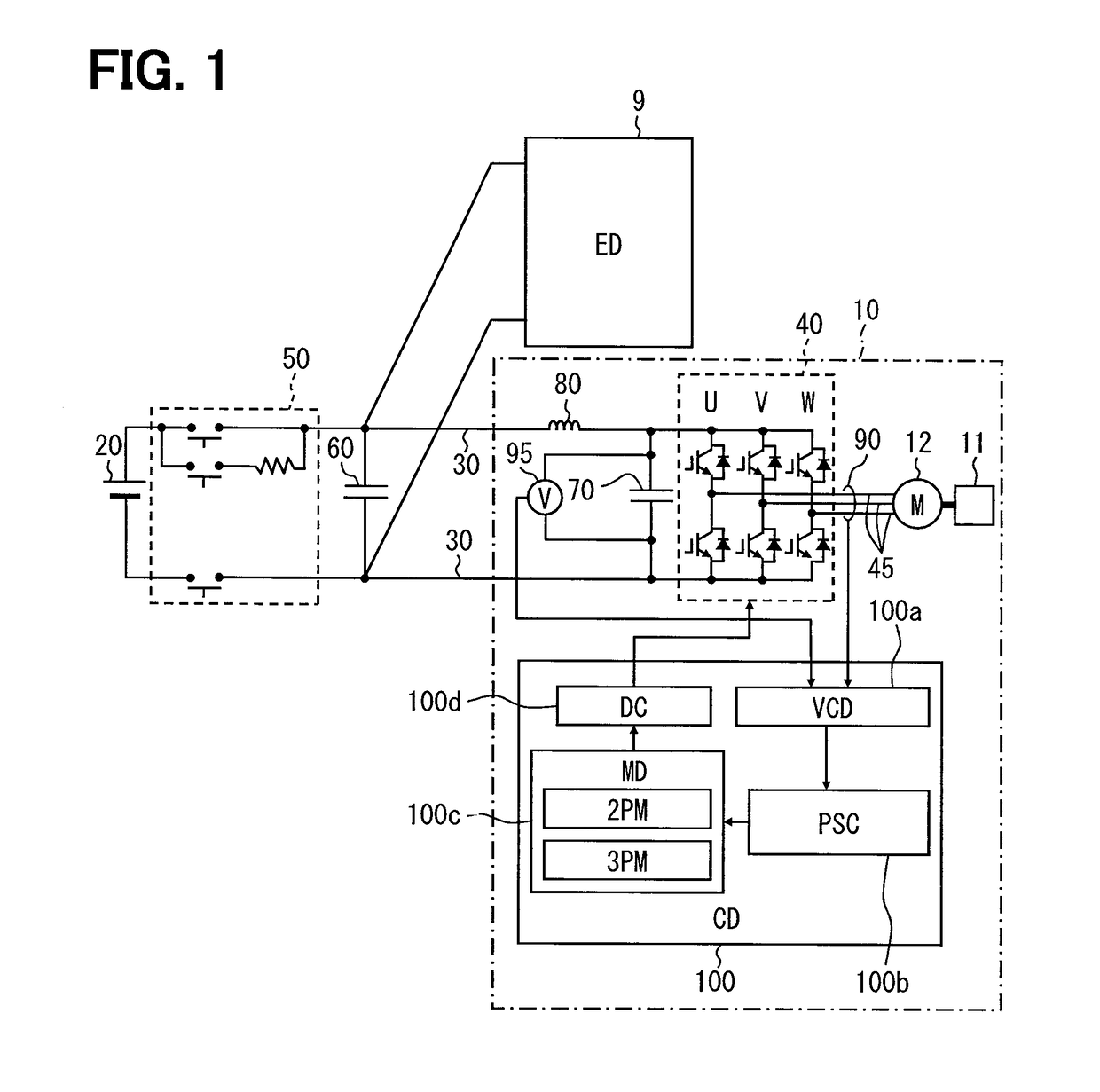
[0023]A first embodiment of the present disclosure will be described with reference to FIGS. 1 to 6.

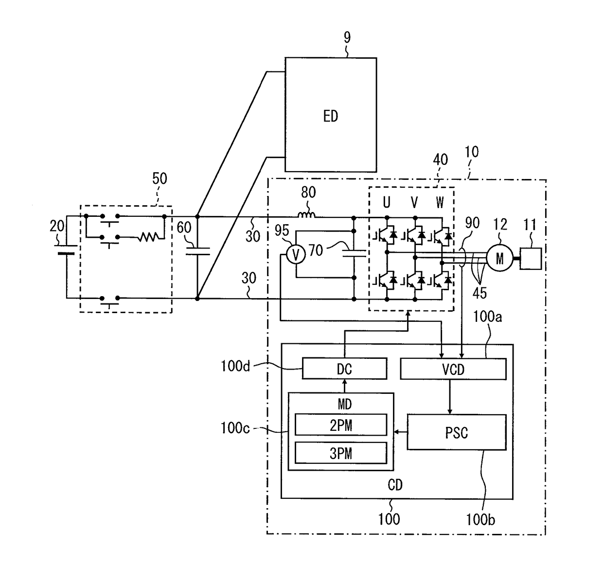
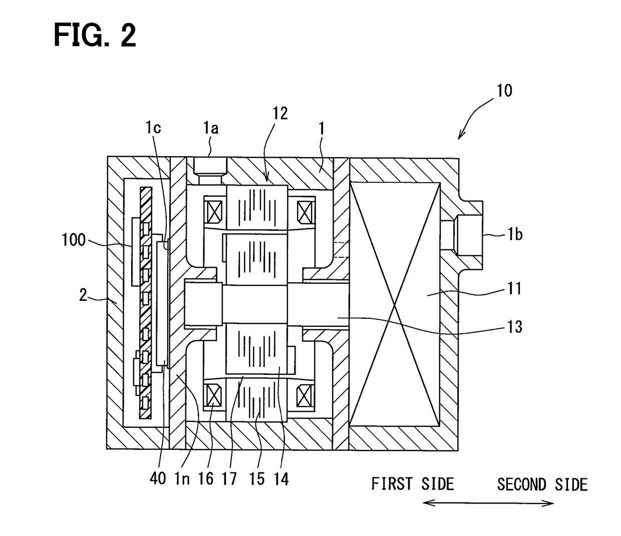
[0024]As shown in FIG. 1, a motor drive device according to this embodiment drives a synchronous motor 12 of an electric compressor 10. According to this embodiment, the synchronous motor 12 corresponds to a motor. The electric compressor 10 is a compressor disposed in the heat pump cycle of a vehicle air conditioner with, for example, carbon dioxide as a refrigerant, and the synchronous motor 12 that is arranged in the electric compressor 10 drives a compression mechanism 11 as a load. The electric compressor 10 is an electric compressor in which the compression mechanism 11 compresses and discharges a vapor refrigerant. For example, the electric compressor 10 compresses a carbon dioxide refrigerant to a critical pressure and discharges it. The synchronous motor 12 according to this embodiment is, for example, a synchronous motor having a four-pole three-phase coil ...


PUM


Abstract

When a control device determines, based on a sampling number in one period of a target modulation factor waveform, that the sampling number is less than a predetermined value in a case where a two-phase modulation scheme is selected and the target rotation number increases, the control device switches a modulation scheme from the two-phase modulation scheme to a three-phase modulation scheme.

Description

CROSS REFERENCE TO RELATED APPLICATIONS[0001]This application is a U.S. National Phase Application under 35 U.S.C. 371 of International Application No. PCT / JP2014 / 002810 filed on May 28, 2014 and published in Japanese as WO 2014 / 196162 A1 on Dec. 11, 2014. This application is based on and claims the benefit of priority from Japanese Patent Application No. 2013-117042 filed on Jun. 3, 2013. The entire disclosures of all of the above applications are incorporated herein by reference.TECHNICAL FIELD[0002]The present disclosure relates to a motor drive device driving a motor by using an inverter circuit.BACKGROUND ART[0003]Conventionally, a motor drive device PWM-modulates a DC voltage into AC by the switching of switching elements of an inverter circuit, outputs the voltage to a motor coil of three phases, and thereby drives a position-sensorless three-phase motor. In such a motor drive device, it is known that a modulation scheme for PWM modulation is selectively switched between a th...

Claims


Application Information

Patent Timeline
Patent Type & Authority Patents(United States)
IPC IPC(8): H02P1/04H02P6/12H02P27/08H02P6/18H02P6/06H02P6/08H02P6/182H02P6/28
CPCH02P27/085
Inventor SAKAI, KOJI
Owner DENSO CORP
Why Eureka
Try Eureka