Solenoid actuated circuit breaker with locking clip

a circuit breaker and solenoid technology, applied in the direction of electrical equipment, emergency protection devices, protective switch operating/release mechanisms, etc., can solve the problems of operator safety hazards, breaker will trip, and interrupt the electrical, so as to facilitate the removal of the actuator module, the effect of preventing or restricting the flexing of the legs toward one another

Active Publication Date: 2017-09-12
CARLING TECH
View PDF8 Cites 9 Cited by
  • Summary
  • Abstract
  • Description
  • Claims
  • Application Information

AI Technical Summary

Benefits of technology

[0015]In some embodiments, the locking clip comprises a generally flat member generally defining a plane, and the locking clip is slideable within the plane from the unlocked position to the locked position. In some embodiments, the locking clip is further moveable from the locked position to the unlocked position so as to facilitate removal of the actuator module from the channel of the housing. In certain of these embodiments, in the unlocked position the locking clip is positioned such that the pair of legs are flexible toward one another, and in the locked position the locking clip is positioned between the legs such that flexing of the legs toward one another is limited or prevented.

Problems solved by technology

If a power surge occurs in a circuit protected by the circuit breaker, for example, the breaker will trip.
This will cause a breaker that was in the “on” position to flip to the “off” position, and will interrupt the electrical power leading from that breaker.
However in some circuits, operating the breaker can produce a dangerous arc, creating a safety hazard for the operator.
In still other circuits, the circuit breaker may be located in a confined or hazardous environment.
However, the lifespan of a solenoid employed to reset a circuit breaker using the switching handle may be limited.
In some cases, the rearming solenoid may wear out or otherwise fail far before the other components of the circuit breaker.
This can require an unacceptably premature replacement of the entire circuit breaker as a unit, increasing costs.
However, this may increase the costs, power consumption, and / or size of the solenoid beyond acceptable limits.

Method used


Image

  • Solenoid actuated circuit breaker with locking clip
  • Solenoid actuated circuit breaker with locking clip
  • Solenoid actuated circuit breaker with locking clip

Examples


Embodiment Construction

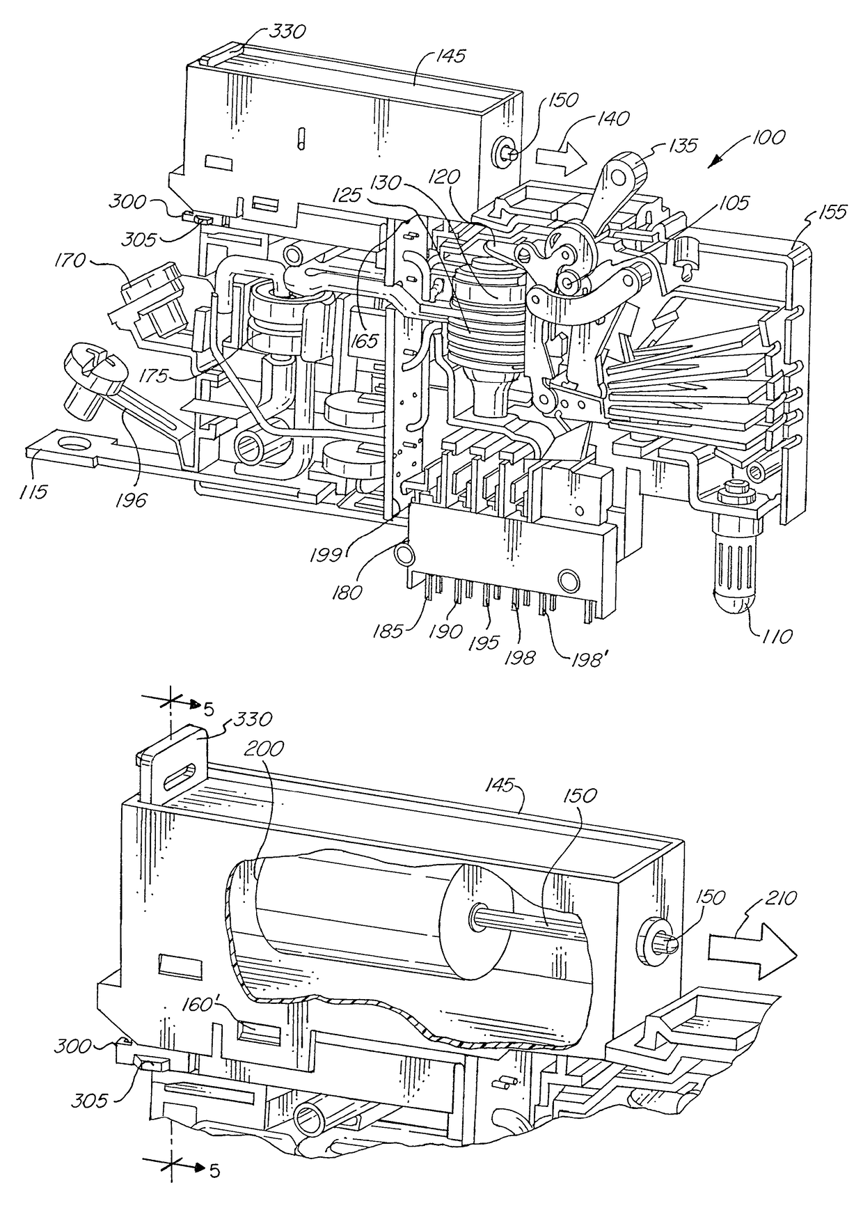
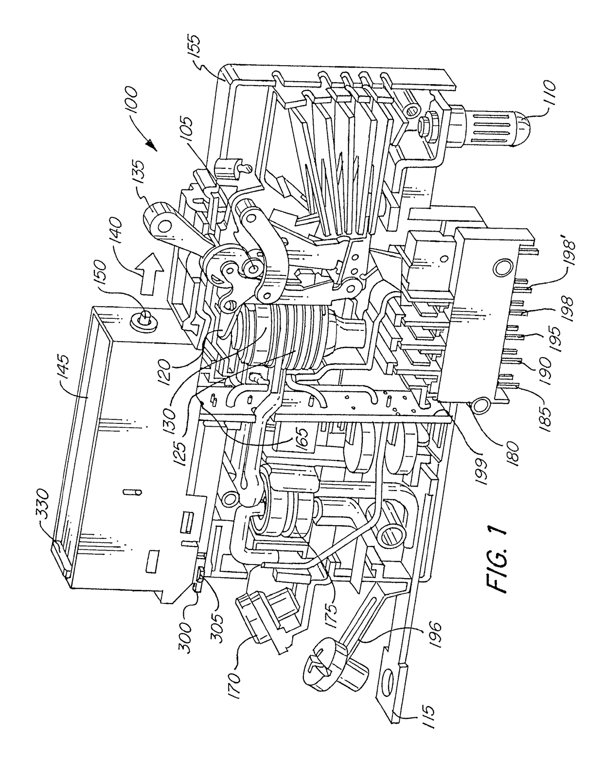
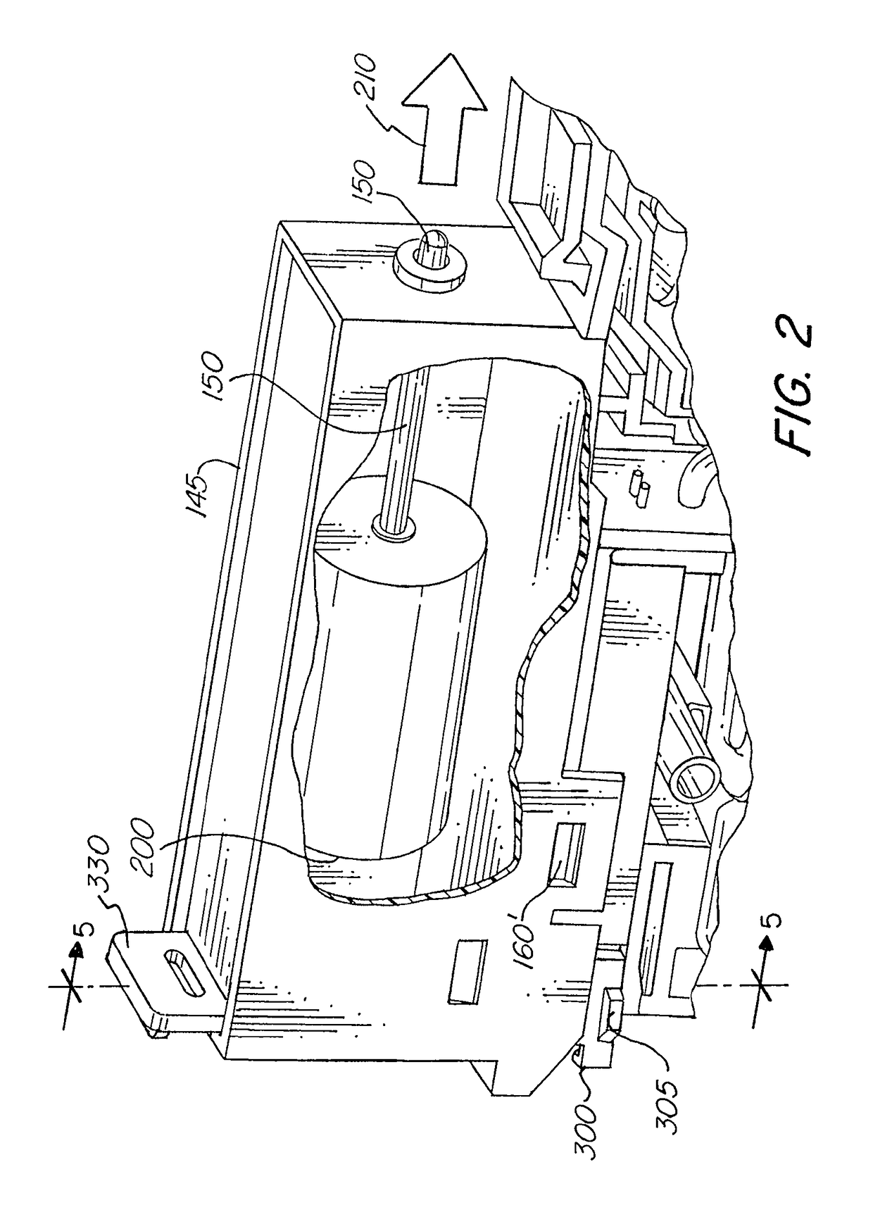
[0028]Referring first to FIGS. 1, 3A, 3B and 4 illustrated is a circuit breaker 100 according to aspects of the invention.

[0029]Circuit breaker 100 includes a circuit breaker mechanism 105 which controls current flow between a line terminal 110 and a load terminal 115. The line terminal 110 receives electricity from a power source such as a generator (not shown), which in some applications is supplied by a power company. Current may flow between line terminal 110 and load terminal 115 when mechanism 105 is in an untripped state. Current cannot flow between line terminal 110 and load terminal 115 when mechanism 105 is in a tripped state.

[0030]Mechanism 105 may be tripped by a tripping mechanism 120. Tripping mechanism 120 may be activated by fault detector 125.

[0031]Fault detector 125 is configured to activate the tripping mechanism 120 when a fault condition occurs, such as excess current. In some applications, fault detector 125 is a solenoid which is disposed in series with the li...


PUM


Abstract

A circuit breaker includes a housing having a channel formed therein, the channel being defined by at least one side wall having a detent formed therein, a circuit breaker mechanism, a switch handle configured to toggle the circuit breaker, and an actuator module adapted to move the switch handle from the off position to the on position. The module includes a flexible portion having a protrusion formed thereon, the protrusion being sized, shaped and located to engage the detent when the module is mounted within the channel. The module also includes a locking clip moveable from an unlocked position, in which flexing of the at least one flexible portion is permitted, and a locked position, in which flexing of the at least one flexible portion is limited or prevented, such that when the module is mounted within the channel, removal of the module is inhibited.

Description

FIELD OF THE INVENTION[0001]The invention relates to remotely operated circuit breakers in general, and more particularly, to circuit breakers having a breaker handle that is remotely operated using a modular solenoid mechanism.BACKGROUND OF THE INVENTION[0002]A circuit breaker is a device that can be used to protect an electrical circuit from damage caused by an overload or a short circuit. If a power surge occurs in a circuit protected by the circuit breaker, for example, the breaker will trip. This will cause a breaker that was in the “on” position to flip to the “off” position, and will interrupt the electrical power leading from that breaker. By tripping in this way, a circuit breaker can prevent a fire from starting on an overloaded circuit, and can also prevent the destruction of the device that is drawing the electricity or other devices connected to the protected circuit.[0003]A standard circuit breaker has a line and a load. Generally, the line receives incoming electricit...

Claims


Application Information

Patent Timeline
Patent Type & Authority Patents(United States)
IPC IPC(8): H01H3/20H01H17/00H01H71/24H01H71/02H01H71/10H01H9/54
CPCH01H71/0228H01H71/1018H01H71/025H01H9/54H01H71/24H01H71/08H01H71/10H01H71/68H01H2071/665
Inventor SORENSON, SR., RICHARDFASANO, MICHAELBUGRYN, JAMES
Owner CARLING TECH
Why Eureka
Try Eureka