Eureka AIR delivers breakthrough ideas for toughest innovation challenges, trusted by R&D personnel around the world.

Systems and methods for detecting patterns in spatio-temporal data collected using an RFID system

a spatio-temporal data and pattern detection technology, applied in the field of interpreting data generated by rfid systems, can solve problems such as limited information concerning the motion of assets, and achieve the effect of enhancing real-world business processes occurring within the sensor cloud

Inactive Publication Date: 2017-09-12
MOJIX
View PDF27 Cites 3 Cited by
  • Summary
  • Abstract
  • Description
  • Claims
  • Application Information

AI Technical Summary

Benefits of technology

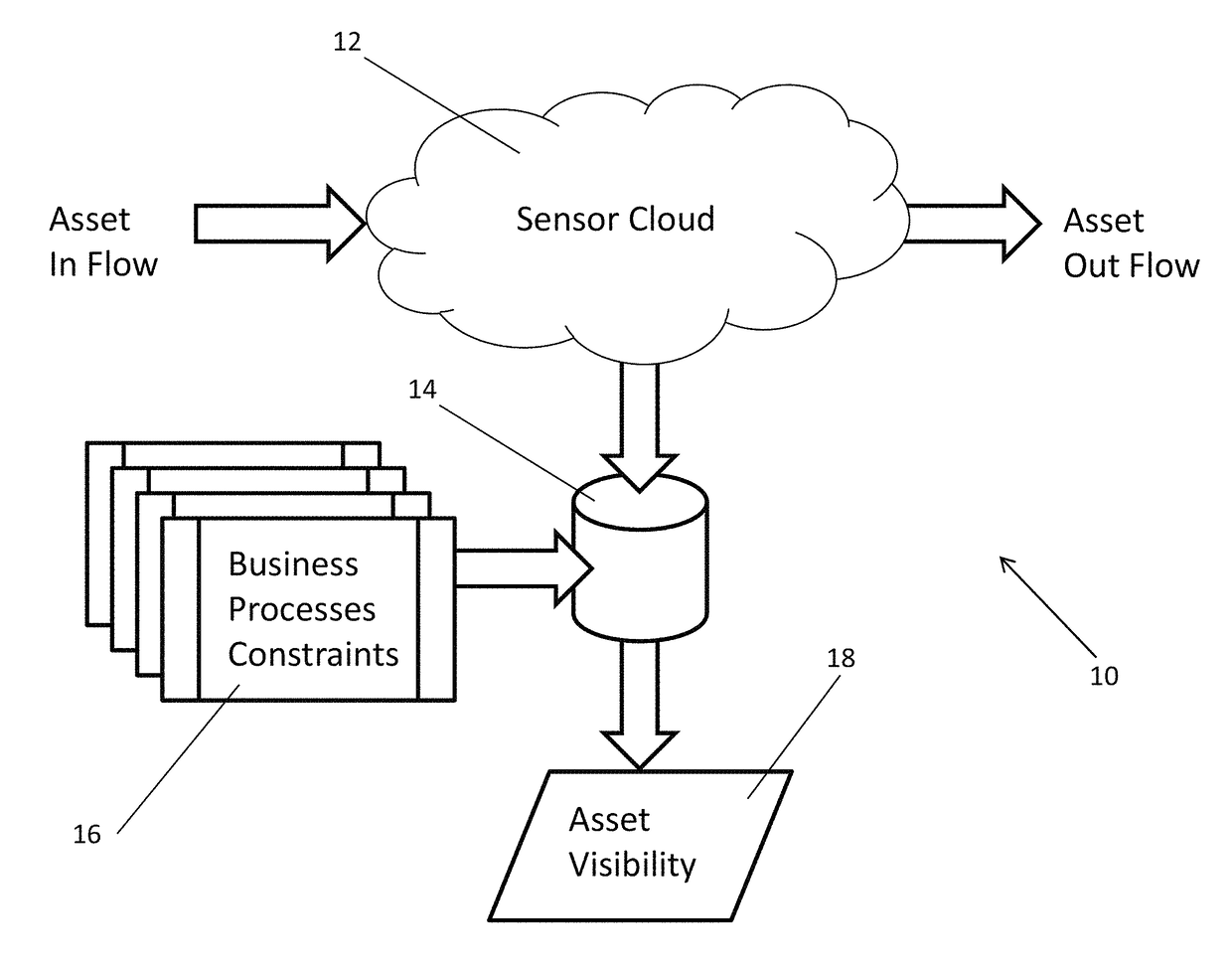
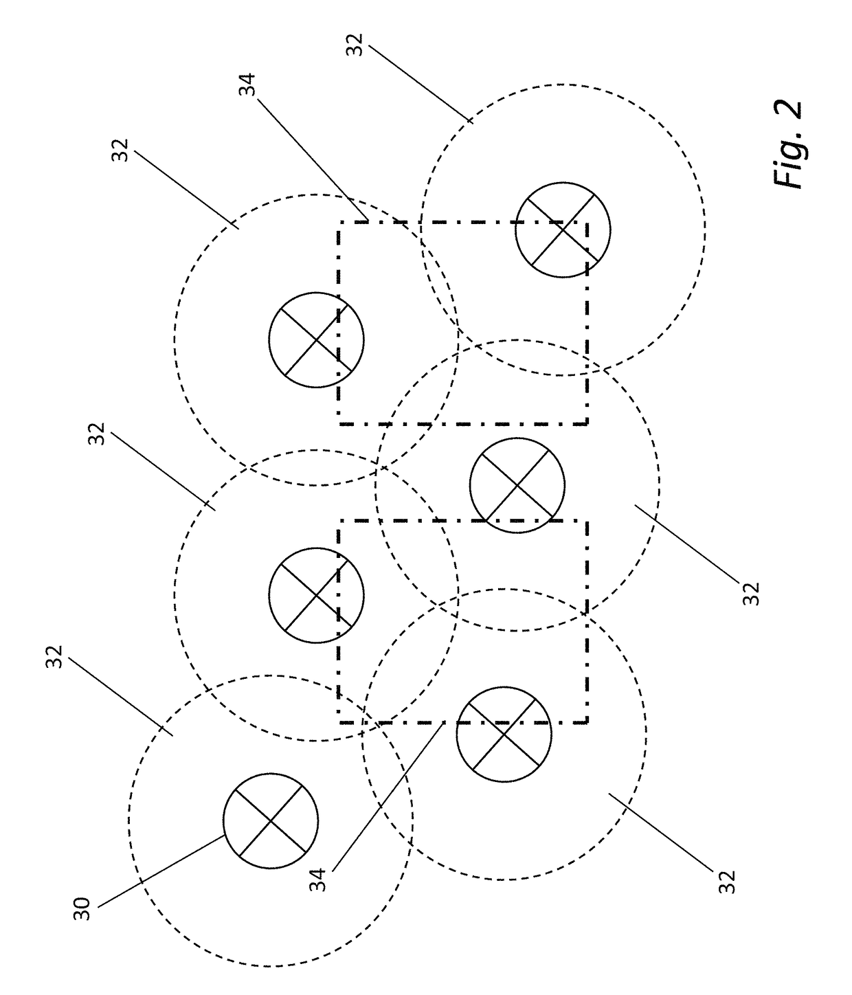
[0005]Systems and methods are described that collect spatio-temporal data using an RFID system that is capable of locating the spatial position of a sensor, which is typically unaware of its location, using an RFID reader system. Such RFID systems and methods can be contrasted with conventional RFID systems in that they are able to determine the location of sensors in space as opposed to with respect to read zones related to the underlying RFID reader infrastructure. In addition, such systems are able to apply fillers to the spatial locations of sensors collected over time (i.e. spatio-temporal data) that involve spatial conditions (i.e. allowed spatial locations) that are defined independently of the read zones of the underlying RFID reader infrastructure. In many embodiments, RFID systems utilize event driven actions and data driven actions to enhance real world business processes occurring within a sensor cloud.

Problems solved by technology

In addition, the information concerning motion of assets is limited to dwell times within and transitions between read zones.

Method used


Image

  • Systems and methods for detecting patterns in spatio-temporal data collected using an RFID system
  • Systems and methods for detecting patterns in spatio-temporal data collected using an RFID system
  • Systems and methods for detecting patterns in spatio-temporal data collected using an RFID system

Examples


Embodiment Construction

[0030]Turning now to the drawings, RFID systems in accordance with embodiments of the invention are described that are configured to build spatio-temporal databases of sensor information and to detect and respond to patterns of data within the spatio-temporal database. In many embodiments, the RFID system is capable of locating the spatial position of sensors within a sensor cloud. The term sensor cloud refers to all of the sensors that are visible within the coverage area of an RFID system. As information is collected from the sensors, the RFID system can build a spatio-temporal database that describes the spatio-temporal trajectories of the sensors. Filters can be applied to the data within the spatio-temporal database based upon a priori knowledge of real world actions or business processes that are likely to be applied to assets within the sensor cloud.

[0031]The ability of an RFID system in accordance with an embodiment of the invention to locate the spatial position of sensors ...


PUM


Abstract

Systems and methods are described that collect spatio-temporal data using an RFID system that is capable of locating the spatial position of a sensor, which is typically unaware of its location. Such systems and methods can be contrasted with conventional RFID systems in that they are able to determine the location of sensors in space as opposed to with respect to read zones related to the underlying RFID reader infrastructure. One embodiment includes an RFID system having a plurality of read zones and configured to obtain the spatio-temporal state of sensors within a sensor cloud, where the spatio-temporal state of each sensor includes sensor information, a time stamp, and a spatial location specified independently of the read zones of the RFID system, a spatio-temporal database configured to store spatio-temporal state of a plurality of sensors over time, and an application server configured to trigger events based upon the detection of at least one condition by applying at least one filter to the data within the spatio-temporal database.

Description

CROSS-REFERENCE TO RELATED APPLICATIONS[0001]The current application claims priority under 35 U.S.C. §119(e) to U.S. Provisional Patent Application No. 61 / 324,282 filed Apr. 14, 2010, entitled “Systems and Methods for Event Generation Based Upon Spatio-Temporal Data Collected Using an RFID System” the disclosure of which is incorporated by reference herein in its entirety.BACKGROUND[0002]The present invention relates generally to radio frequency identification (RFID) and more specifically to interpreting data generated by RFID systems.[0003]A conventional RFID system involves locating RFID tags within read zones of RFID readers. Each of the RFID tags typically includes an identification sequence enabling identification of the tag, when it responds within the read zone of an RFID reader. The precision with which the RFID system can locate an RFID tag is determined by the size of the read zones of each of the RFID readers. A typical RFID system builds a data set from RFID tag reads, w...

Claims


Application Information

Patent Timeline
Patent Type & Authority Patents(United States)
IPC IPC(8): H04Q9/00G06Q10/08
CPCH04Q9/00G06Q10/087H04Q2209/47H04Q2209/753H04Q2209/823H04Q2209/886
Inventor SADR, RAMINJONES, CHRISTOPHER RICHARD
Owner MOJIX
Why Eureka
Eureka Blog
Learn More