Head-up display device

a display device and head-up display technology, applied in the field of head-up display devices, can solve the problems of increased cost, complex structure, damage to the projecting board, etc., and achieve the effects of simplifying structure, reducing cost, and convenient disposal

Active Publication Date: 2017-09-19
LITE ON ELECTRONICS (GUANGZHOU) LTD +1
View PDF2 Cites 0 Cited by
  • Summary
  • Abstract
  • Description
  • Claims
  • Application Information

AI Technical Summary

Benefits of technology

[0005]The objective of the present invention is to provide a HUD device, which has a protecting cover, thereby achieving an effect of protecting a projecting board to prevent the projecting board from being exposed to sunshine or adhered with dust. In addition, the protecting cover is relatively easily disposed, so as to simplify the structure and reduce cost.
[0026]The projecting board assembly of the present invention comprises the holder and the projecting board, wherein the protecting cover can cover the projecting board of the projecting board assembly, thereby achieving the effect of protecting the projecting board to prevent the projecting board from being exposed to sunshine or adhered with dust. Since the protecting cover only covers the projecting board of the projecting board assembly, the protecting cover is more easily disposed and driven, thereby simplifying the structure and reducing cost.
[0027]Moreover, the second guiding mechanism is disposed between the protecting cover and the housing of the present invention. When the driving mechanism drives the projecting board assembly to move towards the displaying position, the protecting cover can be pulled down under guidance of the second guiding mechanism, such that the projecting board is exposed. Therefore, the protecting cover can be driven without other driving mechanisms, further simplifying the structure and reducing cost.

Problems solved by technology

A conventional HUD is not arranged with a protecting cover, so it is easily exposed to sunshine or adhered with dust, thereby resulting in the damage to the projecting board.
However, because the projecting board assembly has a large area, arrangement of a protecting cover is relatively difficult and certainly results in a complex structure and increased cost.

Method used


Image

  • Head-up display device
  • Head-up display device
  • Head-up display device

Examples


Embodiment Construction

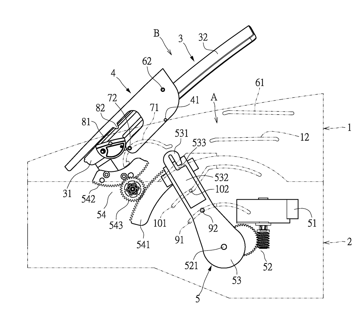
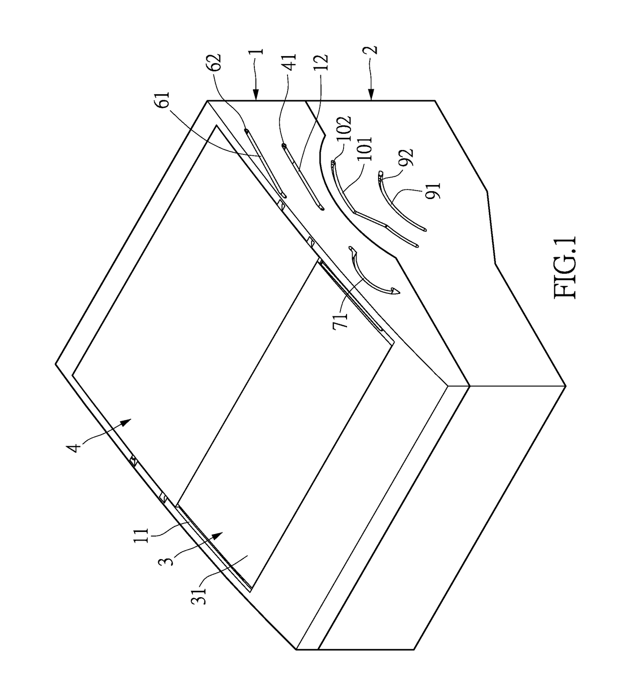
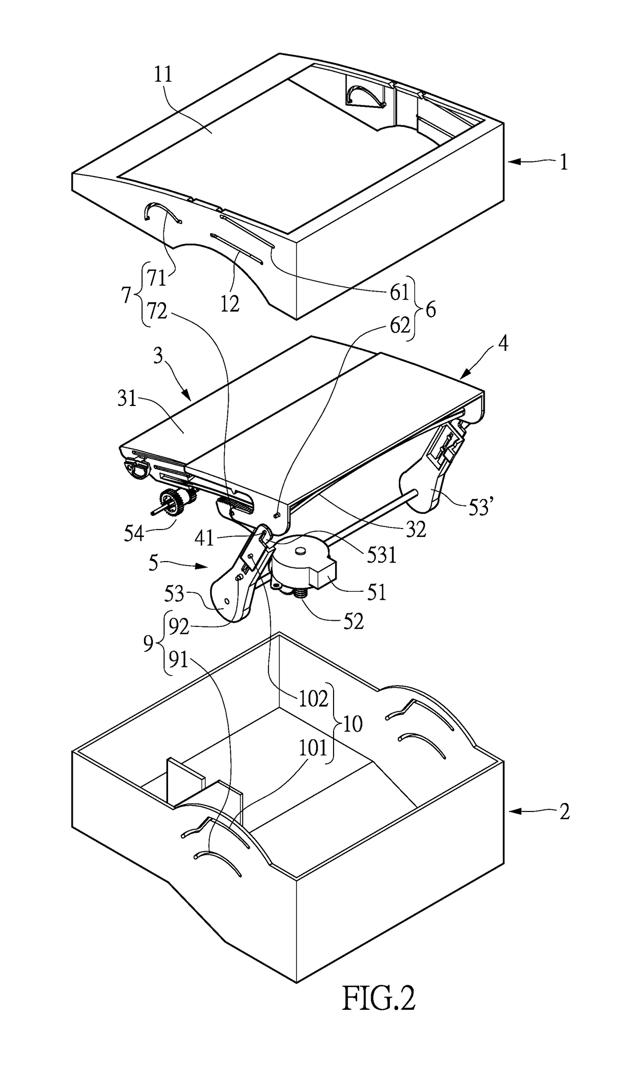
[0038]Referring to FIG. 1 and FIG. 2, the present invention provides a HUD device, particularly a HUD device having a rotary projecting board assembly and comprising a housing 1, a base 2, a projecting board assembly 3, a protecting cover 4, and a driving mechanism 5.

[0039]The housing 1 is hollow. The housing 1 may be a part of an instrument panel housing (e.g. a dashboard) or may be otherwise combined with the instrument panel housing. The housing 1 is formed with an opening 11 such that the projecting board assembly 3 can, through the opening 11, be rotated upwards and extended outside the housing 1 or be rotated downwards and retracted to be at the opening 11 of the housing 1. The base 2 is disposed below the housing 1. The housing 1 and the base 2 can be appropriately fixed onto a vehicle.

[0040]Referring to FIG. 3 to FIG. 5, the projecting board assembly 3 comprises a holder 31 and a projecting board 32. The projecting board 32 is preferably, but not limited to, an arc board. Th...


PUM


Abstract

A head-up display device includes a housing, a base, a projecting board assembly, a protecting cover and a driving mechanism. The projecting board assembly has a holder and a projecting board. The protecting cover is movably arranged on the projecting board assembly, and can be used to cover the projecting board or uncover to expose the projecting board. The projecting board assembly is rotatably arranged above the base by the driving mechanism, and the driving mechanism can drive the projecting board assembly at a storing position or a displaying position. The driving mechanism can drive the protecting cover to be guided by the first guiding mechanism, so as to move the protecting cover. Otherwise, the driving mechanism can pull down the protecting cover by the second guiding mechanism to expose the projecting board, and make the projecting board assembly in the displaying position.

Description

TECHNICAL FIELD[0001]The present invention provides a head-up display (HUD) device, particularly an HUD device having a rotary projecting board assembly.BACKGROUND ART[0002]A head-up display (HUD) is a device for projecting instrument-related information onto a windshield. Compared to a traditional instrument panel, the HUD enables a driver to see required important information without lowering his / her head. Therefore, the driver can see instrument-related information while viewing road conditions.[0003]HUDs having a rotary projecting board assembly have been successively proposed, where vehicle information is displayed by the projecting board assembly which is rotated upwards and extended outward, and when the use of the projecting board assembly is stopped, the projecting board assembly is rotated downwards and retracted into a housing of an instrument panel assembly. A conventional HUD is not arranged with a protecting cover, so it is easily exposed to sunshine or adhered with du...

Claims


Application Information

Patent Timeline
Patent Type & Authority Patents(United States)
IPC IPC(8): G02B27/14G02B27/00G02B27/01
CPCG02B27/0149G02B27/0006G02B2027/0159G02B2027/0163G02B2027/0154
Inventor CHIEN, HUNG-CHANG
Owner LITE ON ELECTRONICS (GUANGZHOU) LTD
Why Eureka
Try Eureka