Shaker systems with class D power amplifiers and methods

a power amplifier and shaker technology, applied in the field of class d power amplifiers, can solve the problems of limited use of microcontrollers for pulse width modulation of high frequency audio amplifiers

Active Publication Date: 2017-09-26
LUS & BUTTS
View PDF4 Cites 0 Cited by
  • Summary
  • Abstract
  • Description
  • Claims
  • Application Information

AI Technical Summary

Problems solved by technology

However, the use of Microcontrollers for pulse width modulation of high frequency audio amplifiers has been limited by the basic instruction cycle time of the Microcontroller.

Method used


Image

  • Shaker systems with class D power amplifiers and methods
  • Shaker systems with class D power amplifiers and methods
  • Shaker systems with class D power amplifiers and methods

Examples


Embodiment Construction

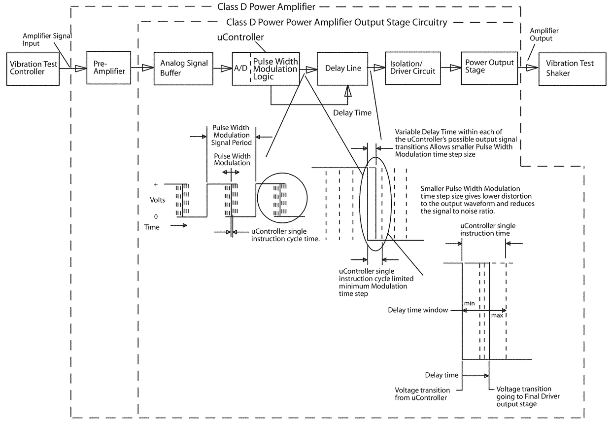
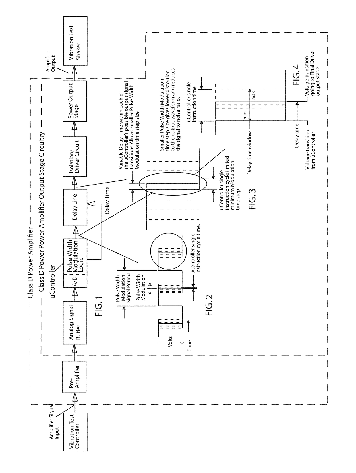
[0008]The circuits and methods disclosed herein allow the use of a relatively inexpensive Microcontroller to establish the timing signals required for pulse width modulation of high frequency audio amplifiers, allowing the achievement of high dynamic range and signal to noise ratio. In accordance with an embodiment of the invention, rather than use a Microcontroller to directly control the output time resolution, a variable time delay circuit is added having a time delay resolution of the order needed to produce the desired output time resolution. With the delay time being controlled by the Microcontroller operating under program control as pulse width modulation logic3, a circuit can be formed that allows the Microcontroller to generate pulse width modulated signals with extremely fine digital time step increments, even though the Microcontroller itself has a much longer cycle time, thus yielding the necessary signal fidelity for high frequency, high dynamic range, high signal-to-n...


PUM

PropertyMeasurementUnit
delay timeaaaaaaaaaa
transition timeaaaaaaaaaa
pulse widthaaaaaaaaaa

Abstract

A shaker test system with a class D power amplifier having an analog to digital converter to receive an analog input signal and convert the analog input signal to a digital signal, pulse width modulation logic coupled to the analog to digital converter to provide a delay time to a delay line to control a transition time of a pulse width modulated signal responsive to an output of the analog to digital converter, and a class D power output stage coupled to the delay line and responsive to the pulse width modulated signal to provide an output of the class D power amplifier stage. The class D amplifier allows use of a low cost microcontroller to obtain very small pulse width increments using a low cost microcontroller to provide a low cost shaker test system incorporating the class D power amplifier.

Description

BACKGROUND OF THE INVENTION[0001]1. Field of the Invention[0002]The present invention relates to the field of class D power amplifiers.[0003]2. Prior Art[0004]Microcontrollers have been commonly used for pulse width modulation of low frequency and low dynamic range signals such as are used in motor control. However, the use of Microcontrollers for pulse width modulation of high frequency audio amplifiers has been limited by the basic instruction cycle time of the Microcontroller. In order to establish a digitally generated audio pulse width modulation signal with high frequency capability and high dynamic range, it is necessary for the digital pulse width modulation time steps to be much shorter than common Microcontroller cycle time.BRIEF DESCRIPTION OF THE DRAWINGS[0005]FIG. 1 is a block diagram of a basic class D amplifier system in Accordance with the present invention.[0006]FIGS. 2-4 illustrate the incremental changes in pulse width of a pulse width modulation pulse using a cla...

Claims


Application Information

Patent Timeline
Patent Type & Authority Patents(United States)
IPC IPC(8): G01M7/00G01N29/00G01M7/02
CPCG01M7/022H03F3/2175
Inventor BUTTS, GARY C.
Owner LUS & BUTTS
Why Eureka
Try Eureka