Sheet manufacturing apparatus

a technology of sheet metal and manufacturing apparatus, which is applied in the direction of chemistry apparatus and processes, gas current separation, papermaking, etc., can solve the problems of slow down of the air flow of the cyclone, stop the supply of defibrated materials to the forming drum, etc., and achieve the effect of preventing the deviation of the classified material in the screening uni

Active Publication Date: 2017-10-03
SEIKO EPSON CORP
View PDF7 Cites 4 Cited by
  • Summary
  • Abstract
  • Description
  • Claims
  • Application Information

AI Technical Summary

Benefits of technology

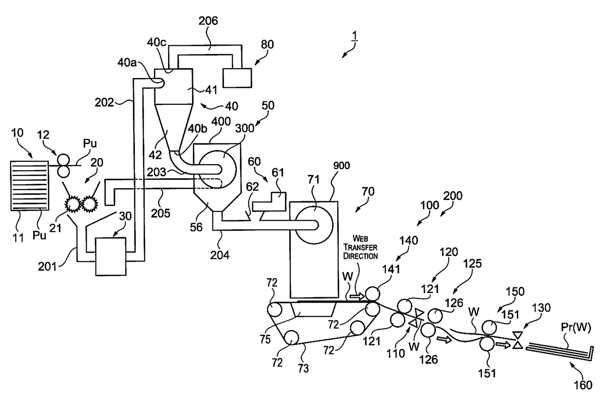
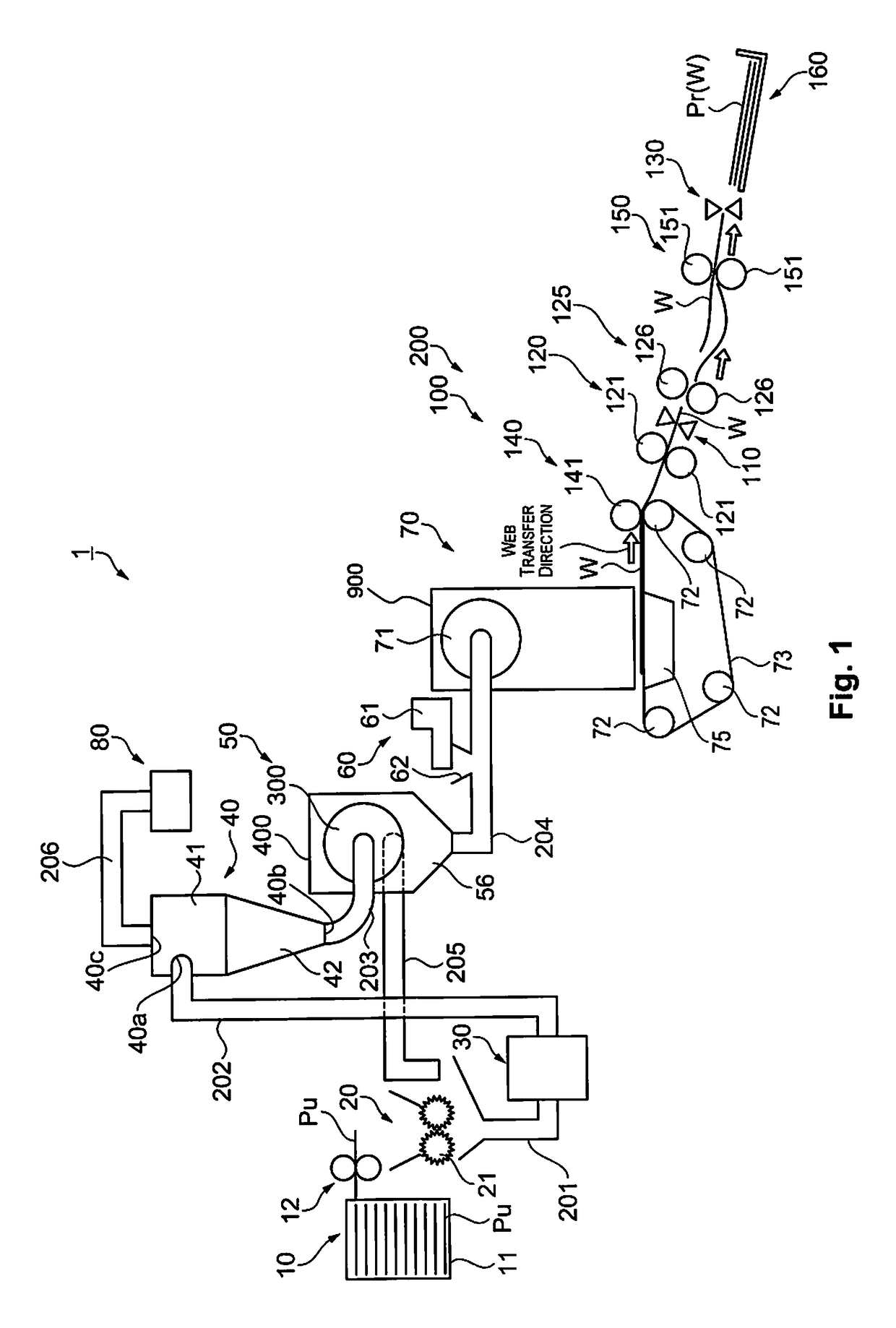
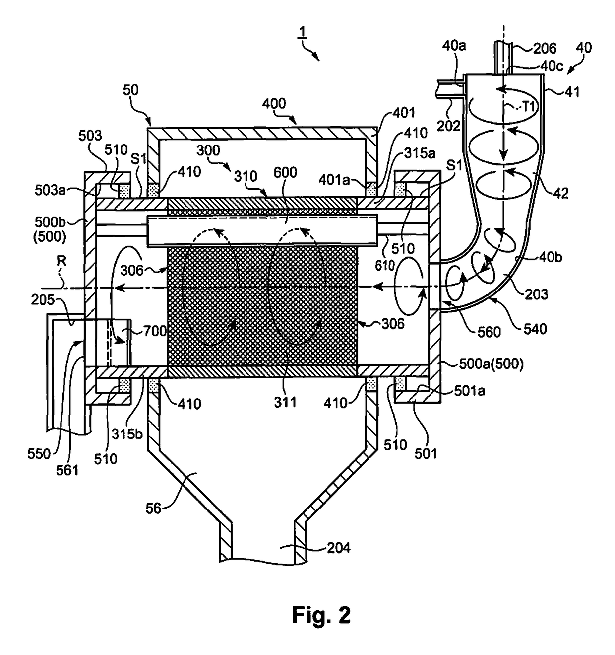
[0009]According to this configuration, the classifier unit classified the introduced material by air flow. Then, the classified material that has been classified is supplied to the screening unit by an air flow, of the aforesaid air flow, that leaves the classifier unit. This makes it possible to efficiently transfer the classified material, without any classified material accumulating midway in the screening unit from the classifier unit. The fibers included in the classified material also will not become entangled with one another, because there is no need to separately install an air-blowing machine such as a blower in the supply and transfer of the classified material from the classifier unit to the screening unit. Moreover, the apparatus configuration can be simplified.
[0013]According to this configuration, the classifier unit is located above the screening unit. In such a case, there is no need for the entirety of the classifier unit to be above the entirety of the screening unit, and it suffices for a part of the classifier unit to be above the entirety of the screening unit. The classifier unit and the screening unit are connected with a conduit that goes downward constantly, and therefore in addition to the air flow, the force of gravity is also applied to the classified material being transferred, making it easier to supply the classified material toward the screening unit. Therefore, it is possible to efficiently transfer the classified material, without any classified material accumulating midway in the screening unit from the classifier unit.
[0015]According to this configuration, the classifier unit and the screening unit are directly connected, and therefore the air flow reliable acts on the classified material being transferred, and the classified material can be reliably supplied to the screening unit without any classified material stopping midway.
[0017]According to this configuration, inclining the classifier unit with respect to the screening unit makes it easier to connect the two directly.
[0019]According to this configuration, the rotation center axis of the screening unit is horizontal, and therefore deviation of the classified material in the screening unit can be prevented.

Problems solved by technology

When the defibrated material is being transferred from the cyclone to the forming drum in the paper recycling apparatus described above, however, a problem emerges in that a part of the second transferring tube connecting the cyclone and the forming drum has a horizontal portion and therefore the momentum of the air flow of the cyclone ends up gradually weakening in this horizontal portion, and the defibrated material ends up accumulating in the horizontal portion, thus stopping up supply of the defibrated material to the forming drum.

Method used


Image

  • Sheet manufacturing apparatus
  • Sheet manufacturing apparatus
  • Sheet manufacturing apparatus

Examples


modification example 1

[0090]In the embodiment above, the classifier unit 40 and the screening unit 50 were connected with the tubing 203, but there is no limitation to this configuration. For example, the configuration may be one where the classifier unit 40 and the screening unit 50 are directly connected without any intervening conduit or the like. FIG. 8 is a detail diagram illustrating a classifier unit and screening unit as in a modification example. As illustrated in FIG. 8, a classifier unit 40′ and a screening unit 50′ are directly connected. So doing reduces the places where the classified material collects between the classifier unit 40′ and the screening unit 50′, and therefore makes it possible for the classified material to be reliably transferred from the classifier unit 40′ to the screening unit 50′. Moreover, the classifier unit 40′ has a cylindrical or conical part, and an imaginary center line C1′ of the cylindrical or conical part is inclined with respect to the vertical direction. So ...

modification example 2

[0091]In the embodiment above, the inner peripheral surface of the opening unit 310 of the drum unit 300 was a smooth surface, but there is no limitation to this configuration. For example, there may be irregularities on the inner peripheral surface of the opening unit 310. FIG. 9 is a schematic unit illustrating the configuration of a classifier unit as in a modification example. As illustrated in FIG. 9, convexities 333 are formed on the inner peripheral surface of the opening unit 310, and this forms irregularities on the inner peripheral surface. The shape of the convexities 333 may be a shape that extends along the direction of extension of the rotation center axis R of the drum unit 300, or may be dots. So doing allows the material to move more easily along with the drum unit 300, due to the irregularities, and makes it possible to improve the sieving function.

modification example 3

[0092]The rotation center axis of the drum unit 300 was the horizontal direction in the embodiment above, but is not limited thereto. For example, the configuration may be one where the rotation center axis R of the drum unit 300 is inclined with respect to the horizontal plane. In such a case, the rotation center axis R of the drum unit 300 is inclined with respect to the horizontal plane so that the discharge unit 550 side is lower than the introduction unit 540 side. So doing makes it possible to improve the ability to discharge the residual material, because the residual material inside the drum unit 300 moves to the discharge unit 550 side due to the force of gravity.


PUM

PropertyMeasurementUnit
angleaaaaaaaaaa
rotationaaaaaaaaaa
momentumaaaaaaaaaa

Abstract

A sheet manufacturing apparatus includes a classifier unit configured to classify by air flow an introduced material that has been introduced, a screening unit configured to allow a classified material, which comprises fibers, that has been classified by the classifier unit to pass through a plurality of openings to screen the classified material, and a forming unit configured to use a passed material that has passed through the openings to form a sheet. The classified material is supplied to the screening unit by the air flow.

Description

CROSS-REFERENCE TO RELATED APPLICATIONS[0001]This application claims priority to Japanese Patent Application No. 2013-266611 filed on Dec. 25, 2013 and Japanese Patent Application No. 2014-033785 filed on Feb. 25, 2014. The entire disclosure of Japanese Patent Application Nos. 2013-266611 and 2014-033785 is hereby incorporated herein by reference.BACKGROUND[0002]Technical Field[0003]The present invention relates to a sheet manufacturing apparatus.[0004]Related Art[0005]Conventionally known is a paper recycling apparatus having a dry-type defibrating unit for breaking up and defibrating paper, a first transferring unit for transferring a defibrated material that has been defibrated at the dry-type defibrating unit, a classifier unit for classifying by air flow and de-inking the defibrated material that has been transferred at the first transferring unit, a second transferring unit for transferring the defibrated material that has been de-inked at the classifier unit, and a paper form...

Claims


Application Information

Patent Timeline
Patent Type & Authority Patents(United States)
IPC IPC(8): B07B9/00D21B1/06D21B1/32D21D5/18D21D5/24D21F9/00
CPCB07B9/00D21B1/06D21B1/32D21D5/18D21D5/24D21F9/00Y02W30/646B07B9/02Y02W30/64
Inventor MIYAZAWA, KAZUMA
Owner SEIKO EPSON CORP
Why Eureka
Try Eureka