Attachment structure between exterior member and posterior attaching component

a technology of attaching component and exterior member, which is applied in the direction of vehicle components, electric/fluid circuits, transportation and packaging, etc., can solve the problems of increasing rigidity, difficult to cope, and constraining resin molding, so as to facilitate fine adjustment, increase rigidity, and cope easy

Active Publication Date: 2017-10-03
YAZAKI CORP
View PDF64 Cites 8 Cited by
  • Summary
  • Abstract
  • Description
  • Claims
  • Application Information

AI Technical Summary

Benefits of technology

[0011]In other words, the exterior member has a straight tube section formed to be elongated, and the straight tube section needs to have a certain level of rigidity such that the shape is maintained in the straight state after the wiring of the wire harness. However, since the flexible tube section having the bellows tube shape, which is continuous to the straight tube section, is formed to be thin in thickness and has to be a bendable section, the straight tube section may, conversely, become thick in thickness such that rigidity is increased, which results in constraints on resin molding.
[0013]One or more embodiments of the present invention are provided in consideration of the circumstances described above, and thus, an object thereof is to provide an attachment structure between an exterior member and a posterior attaching component in which it is possible to flexibly dispose an attachment position of the posterior attaching component and it is possible to increase rigidity.
[0018]In the embodiment according to the first aspect, since the protrusion groups, which are formed of the multiple protrusions, are formed on the outer surface of the straight tube section in the exterior member, it is possible to adjust the attachment position of the posterior attaching component depending on the pitch at which the protrusions are arranged. In other words, in a case where the attachment position of the posterior attaching component needs to be changed, it is possible to easily cope with the change when the insertion position of the annular wall formed in the posterior attaching component is changed. Accordingly, according to the present embodiment, an effect that it is possible to flexibly dispose the attachment position of the posterior attaching component is achieved. In addition, according to the embodiment, since multiple protrusions are formed on the outer surface of the straight tube section, it is possible for the straight tube section to obtain rigidity due to the multiple protrusions and further due to the arrangement state in the plurality of rows. Accordingly, according to the embodiment, an effect that it is possible to increase the rigidity is achieved.
[0019]In the embodiment according to the second aspect, the positions of the protrusions are shifted in the one protrusion group and the adjacent protrusion group of the plurality of protrusion groups. Therefore, even when the attachment position of the posterior attaching component needs to be more finely adjusted, an effect that it is possible to easily cope with the fine adjustment is achieved.
[0020]In the embodiment according to the third aspect, since the protrusions are formed to have substantially the rectangular shape which has the width in the tube axial direction longer than the width in the circumferential direction of the outer surface, the shape causes movement of the posterior attaching component in the tube axial direction to be easily regulated and the shape causes rotation of the posterior attaching component to be easily guided. As a result, an effect that it is possible to contribute to improvement of workability in the wiring of the wire harness is achieved.
[0021]In the embodiment according to the fourth aspect, since the clamp is employed as the posterior attaching component, an effect that it is possible to flexibly dispose the attachment position of the clamp is achieved. In addition, according to the embodiment, an effect that it is possible to set the annular wall which is inserted into between the protrusions at more appropriate positions is achieved.

Problems solved by technology

Incidentally, in the related art described above, since the attachment position of the clamp is determined, and then the clamp is attached at the position, it may be difficult to cope with a case where an attachment position of the clamp is changed in the wiring of the wire harness.
In addition, in the related art described above, since a long wire harness is provided and thus, the long exterior member is provided, the following problems may arise.
However, since the flexible tube section having the bellows tube shape, which is continuous to the straight tube section, is formed to be thin in thickness and has to be a bendable section, the straight tube section may, conversely, become thick in thickness such that rigidity is increased, which results in constraints on resin molding.
In addition, when the straight tube section is merely increased in thickness, the weight is increased as a whole, and, as a result, it may be difficult to achieve a lightweight wire harness.

Method used


Image

  • Attachment structure between exterior member and posterior attaching component
  • Attachment structure between exterior member and posterior attaching component
  • Attachment structure between exterior member and posterior attaching component

Examples


example

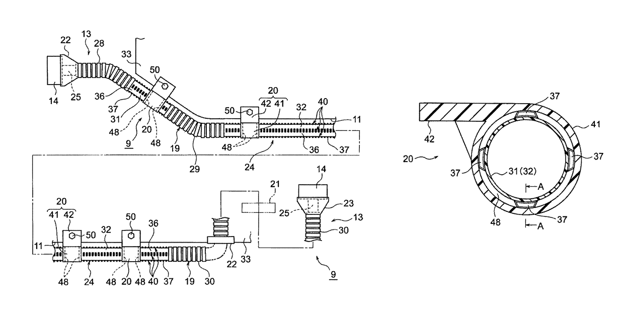
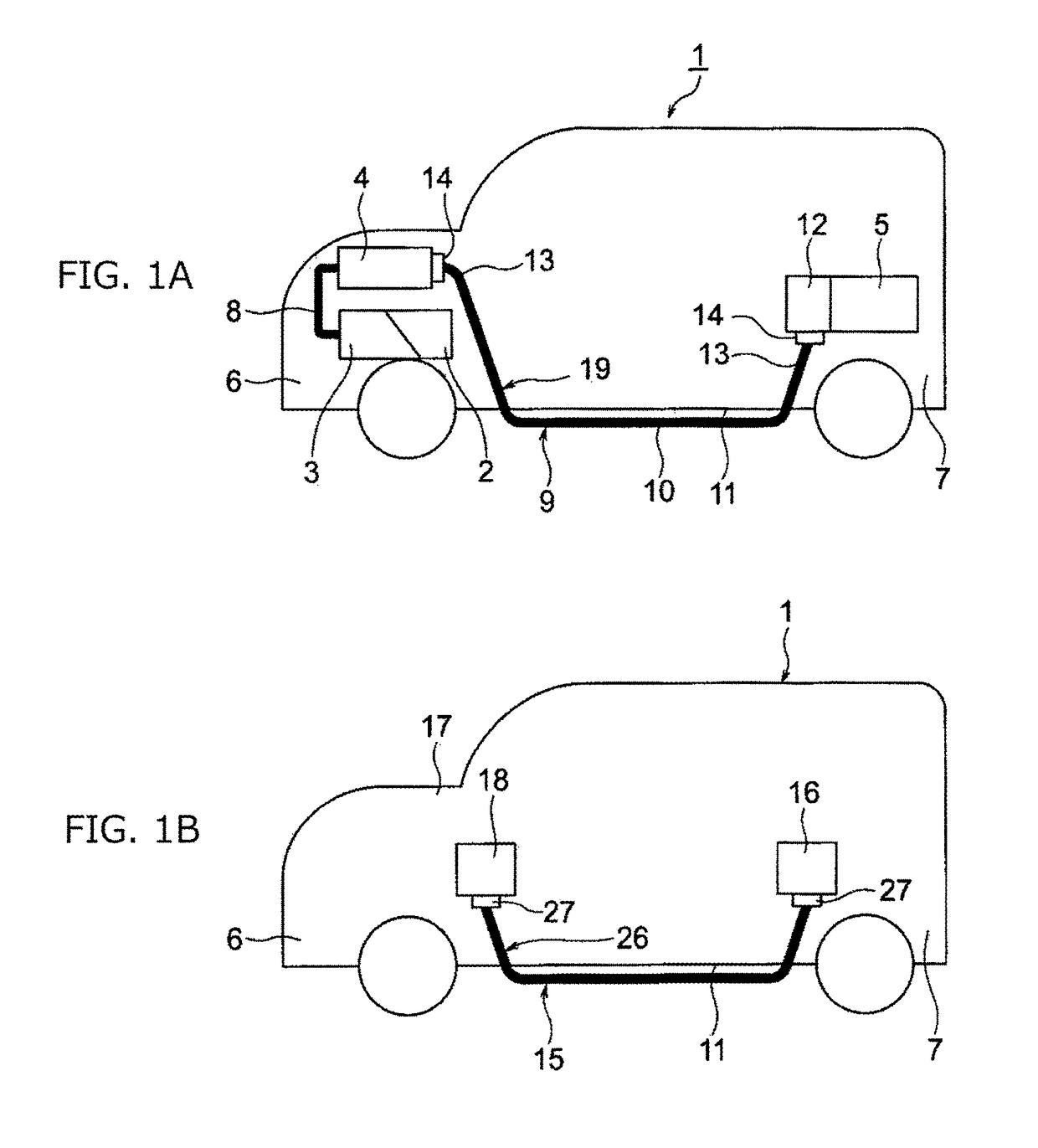
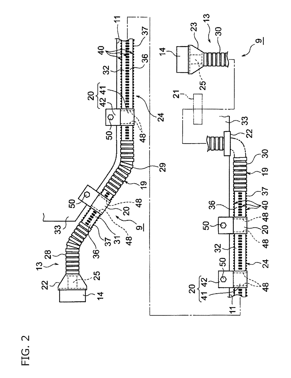
[0030]Hereinafter, Example 1 will be described with reference to the drawings. FIGS. 1A and 1B are views of wire harnesses which employ a structure according to the present invention; FIG. 1A is a view schematically illustrating a wiring state of a high-voltage wire harness and FIG. 1B is a view schematically illustrating a wiring state of another wire harness than FIG. 1A. FIG. 2 is a view of an outline illustrating a configuration and a fixing state of the wire harness in FIG. 1A. FIG. 3 is a view of an exterior member in FIG. 2. FIGS. 4A and 4B are perspective views of straight tube sections. FIGS. 5A and 5B are enlarged views of main parts of the straight tube sections. FIG. 6 is a perspective view of a clamp in FIG. 2. FIGS. 7A to 7C are sectional views of an attachment section between the straight tube section and the clamp.

[0031]In the present example, the present invention is employed to the wire harness which is wired in a hybrid automobile (or an electrical automobile and ...


PUM


Abstract

An attachment structure between an exterior member and a posterior attaching component to be attached to the exterior member includes: the exterior member that has a tube body shape and is included in a wire harness that has one or a plurality of conductive paths, the exterior member covering the conductive path. The exterior member includes a straight tube section that has a straight shape and is an attachment target section of the posterior attaching component. Multiple protrusions are formed on an outer surface of the straight tube section and include a plurality of protrusion groups arranged in rows, each of the plurality of protrusion groups includes the protrusions arranged at predetermined pitches in a tube axial direction, and the multiple protrusions are configured to be inserted into an annular wall of the posterior attaching component.

Description

CROSS REFERENCE TO RELATED APPLICATION[0001]This application is based on Japanese Patent Application (No. 2015-13963) filed on Jan. 28, 2015, the contents of which are incorporated herein by reference. Also, all the references cited herein are incorporated as a whole.BACKGROUND OF THE INVENTION[0002]1. Technical Field[0003]One or more embodiments of the present invention relate to an attachment structure between an exterior member of a wire harness and a posterior attaching component which is posteriorly attached to the exterior member.[0004]2. Background Art[0005]For example, a wire harness is used to electrically connect high voltage machines mounted in a hybrid automobile or an electric automobile. Patent Document 1 to be described below discloses a wire harness which is configured to include a conductive path and a synthetic resin exterior member which protects the conductive path. The exterior member includes a flexible tube section having a bellows tube shape and a straight tu...

Claims


Application Information

Patent Timeline
Patent Type & Authority Patents(United States)
IPC IPC(8): B60R16/02
CPCB60R16/0215
Inventor OGA, TATSUYAADACHI, HIDEOMIYAMAZAKI, RYUTARO
Owner YAZAKI CORP
Why Eureka
Try Eureka