Flexible coupling system

a coupling system and flexible technology, applied in the field of flexible coupling systems, can solve the problem that the rest of the human body cannot be excluded, and achieve the effect of reducing the length of the body

Active Publication Date: 2017-10-10
JOHNSON ALWYN P
View PDF31 Cites 1 Cited by
  • Summary
  • Abstract
  • Description
  • Claims
  • Application Information

AI Technical Summary

Benefits of technology

[0003]Disclosed herein is a system for coupling two separate structural members while providing a measure of both flexibility of the connection and resistance to the full range-of-motion.

Problems solved by technology

While utility may be of primary concern, the limitations of the rest of the human body cannot be ignored.

Method used


Image

  • Flexible coupling system
  • Flexible coupling system
  • Flexible coupling system

Examples


Embodiment Construction

[0021]Selected embodiments of the present invention will now be explained with reference to the drawings. It will be apparent to those skilled in the art from this disclosure that the following descriptions of the embodiments of the present invention are provided for illustration only and not for the purpose of limiting the invention as defined by the appended claims and their equivalents.

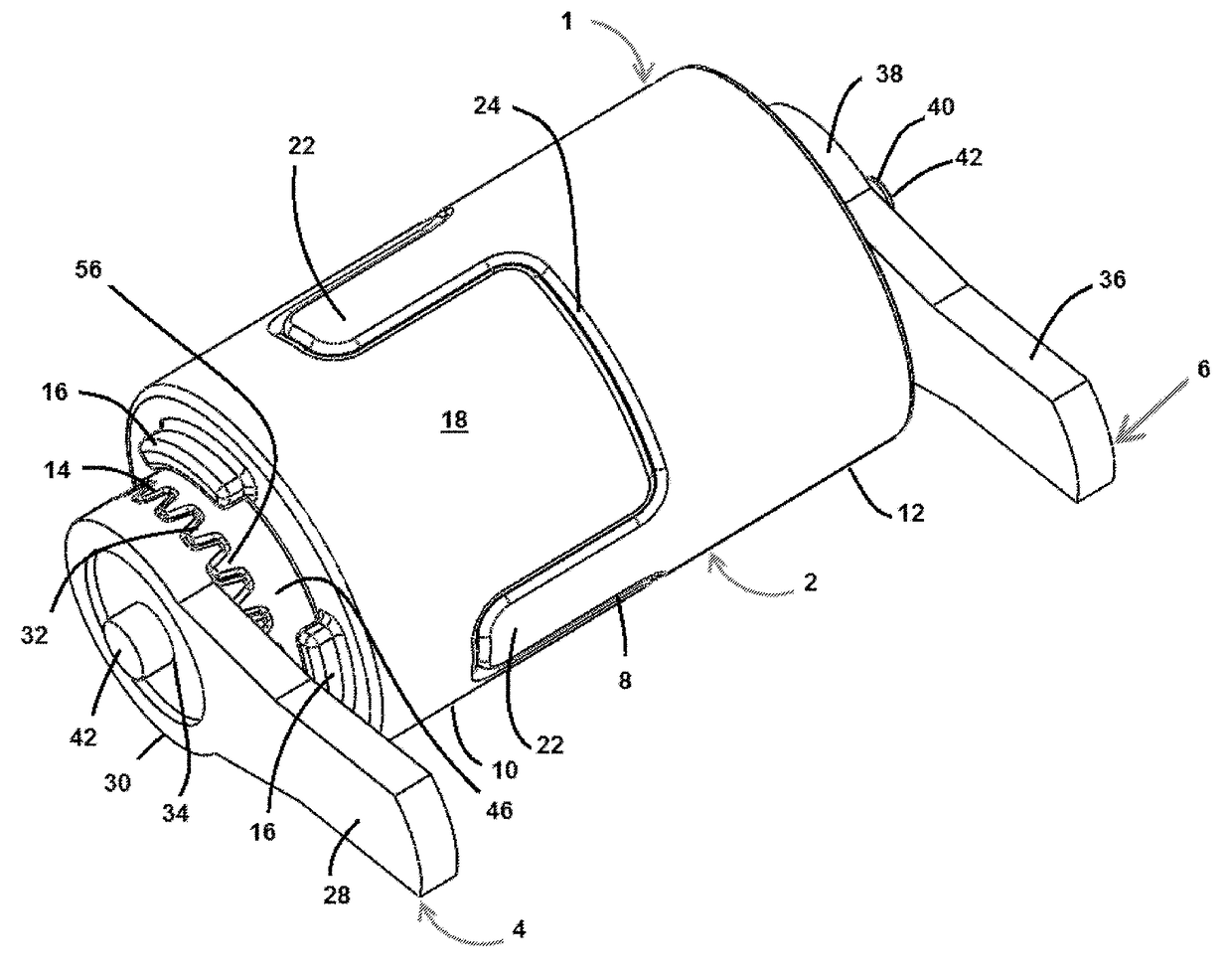
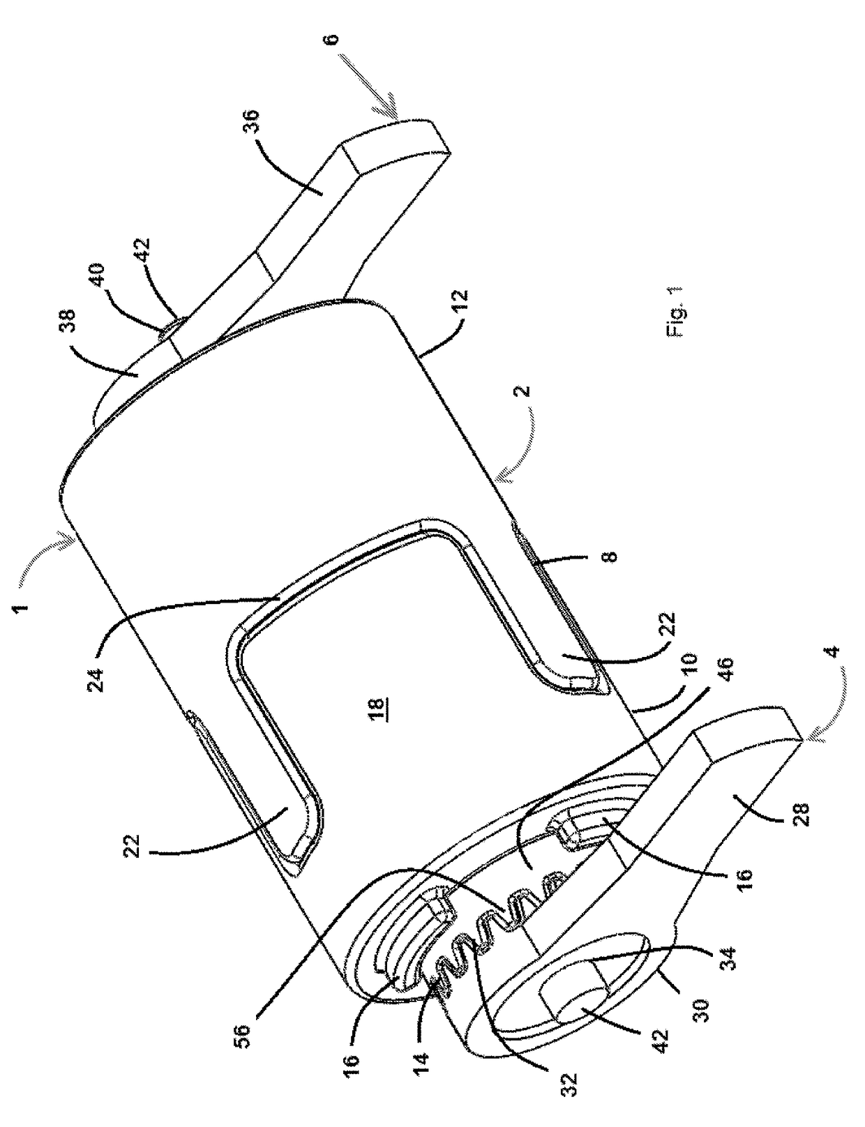
[0022]Referring initially to FIG. 1, a flexible coupling system 1 is illustrated in accordance with a first embodiment of the present invention. The flexible coupling system 1 includes a coupling assembly 2, a first arm mechanism 4 and a second arm mechanism 6. The first arm mechanism 4 and the second arm mechanism 6 connect to the coupling assembly 2 at respective ends of the coupling assembly 2. The first arm mechanism 4 and the second arm mechanism 6 are for connection with that which requires dampening or selective flexibility. For example, the flexible coupling system 1 may be positioned at a ...


PUM


Abstract

An apparatus for joining two members, comprising a central assembly within a first housing, the central assembly comprising a rotor or rotational member, a pin attached at one end to the rotor or rotational member, a base circumferentially disposed about the pin and attached thereto, a resistance member in connection with the pin, at least one compression member in connection with the resistance member, at least one intermediary member disposed between the at least one compression member and the base, a second housing in connection with the pin and first and second arm mechanisms attached at opposing distal ends of the pin.

Description

BACKGROUND OF THE INVENTION[0001]A joint between two structural members requires a connecting point and a manner of connecting the two members. Depending upon the type of joint and its requirements for operation, the joint may be either fixed or movable. In the case of a movable joint, the connection should be flexible. This flexibility allows the joint to operate within a defined range-of-motion. When unrestricted range-of-motion of a joint is not desired, the manner of connection must provide at least some resistance to the members.[0002]The development of modern prostheses and artificial limbs provides a specific example of these requirements in practice. Any artificial limb containing a joint must travel within a natural range-of-motion in order to approximate human anatomy and thus allow the most utility possible. While utility may be of primary concern, the limitations of the rest of the human body cannot be ignored. For this reason, any artificial joint must also provide resi...

Claims


Application Information

Patent Timeline
Patent Type & Authority Patents(United States)
IPC IPC(8): A61F2/50A61F5/01
CPCA61F2/50A61F5/01Y10T16/540345A61F2002/5007
Inventor JOHNSON, ALWYN P.
Owner JOHNSON ALWYN P
Why Eureka
Try Eureka