Three-rod type device and method for measuring robot tool coordinate system

A technology of tool coordinate system and measuring device, applied in the direction of mechanical measuring device, measuring device, adopting mechanical device, etc., to achieve the effect of enhanced flexibility, simple structure and convenient installation

Inactive Publication Date: 2019-11-05
BEIJING UNION UNIVERSITY
View PDF10 Cites 0 Cited by
  • Summary
  • Abstract
  • Description
  • Claims
  • Application Information

AI Technical Summary

Problems solved by technology

[0004] In order to solve the above problems, the present invention aims to provide an auxiliary measurement device for calibration of the origin of the tool coordinate system (hereinafter referred to as the TCP point) and the measurement of the tool coordinate system when the industrial robot is debugged, which can solve the situation where the robot is not equipped with a robot hand tool The problem of determining the TCP point under

Method used


Image

  • Three-rod type device and method for measuring robot tool coordinate system
  • Three-rod type device and method for measuring robot tool coordinate system
  • Three-rod type device and method for measuring robot tool coordinate system

Examples


Embodiment 1

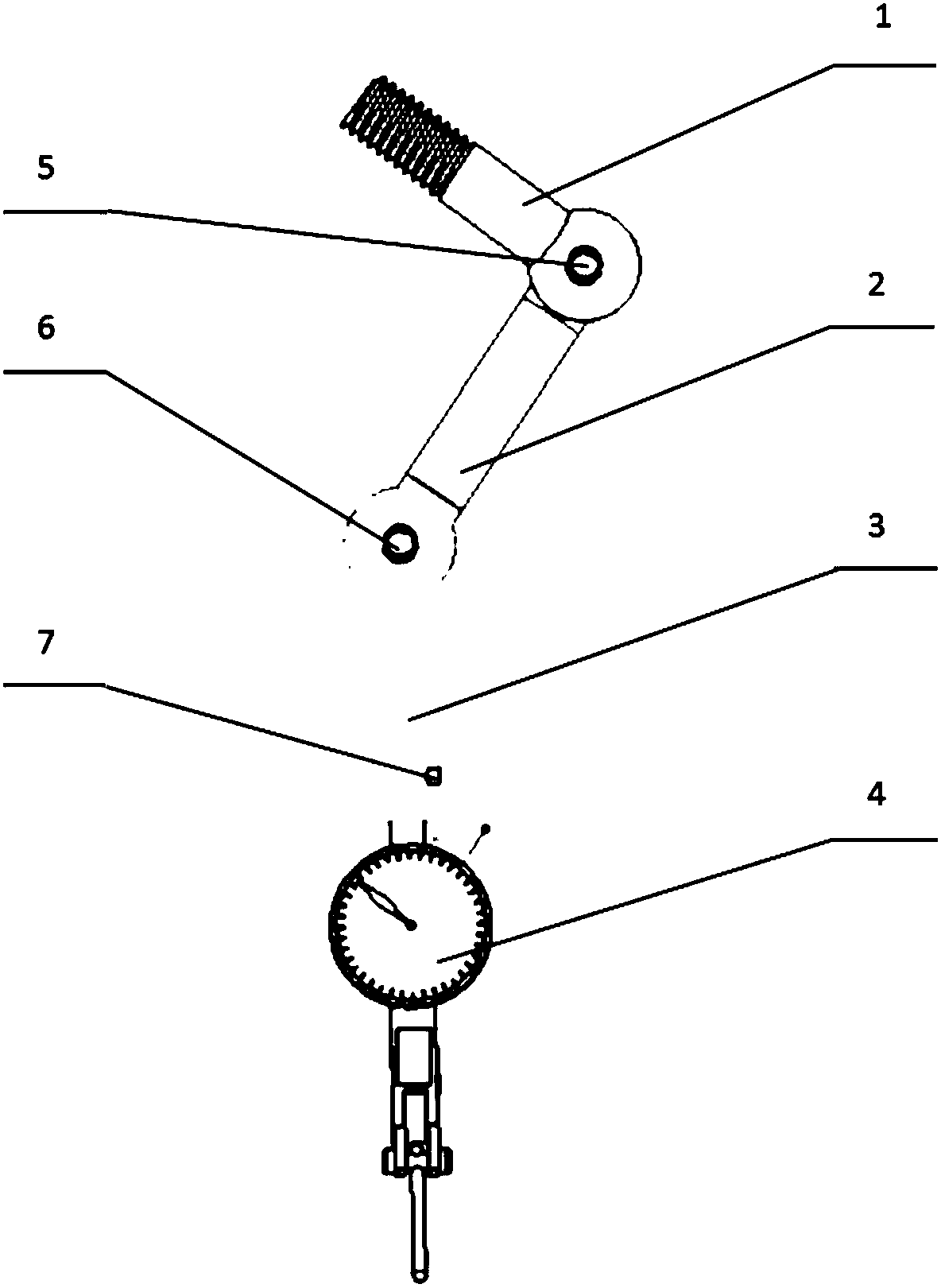
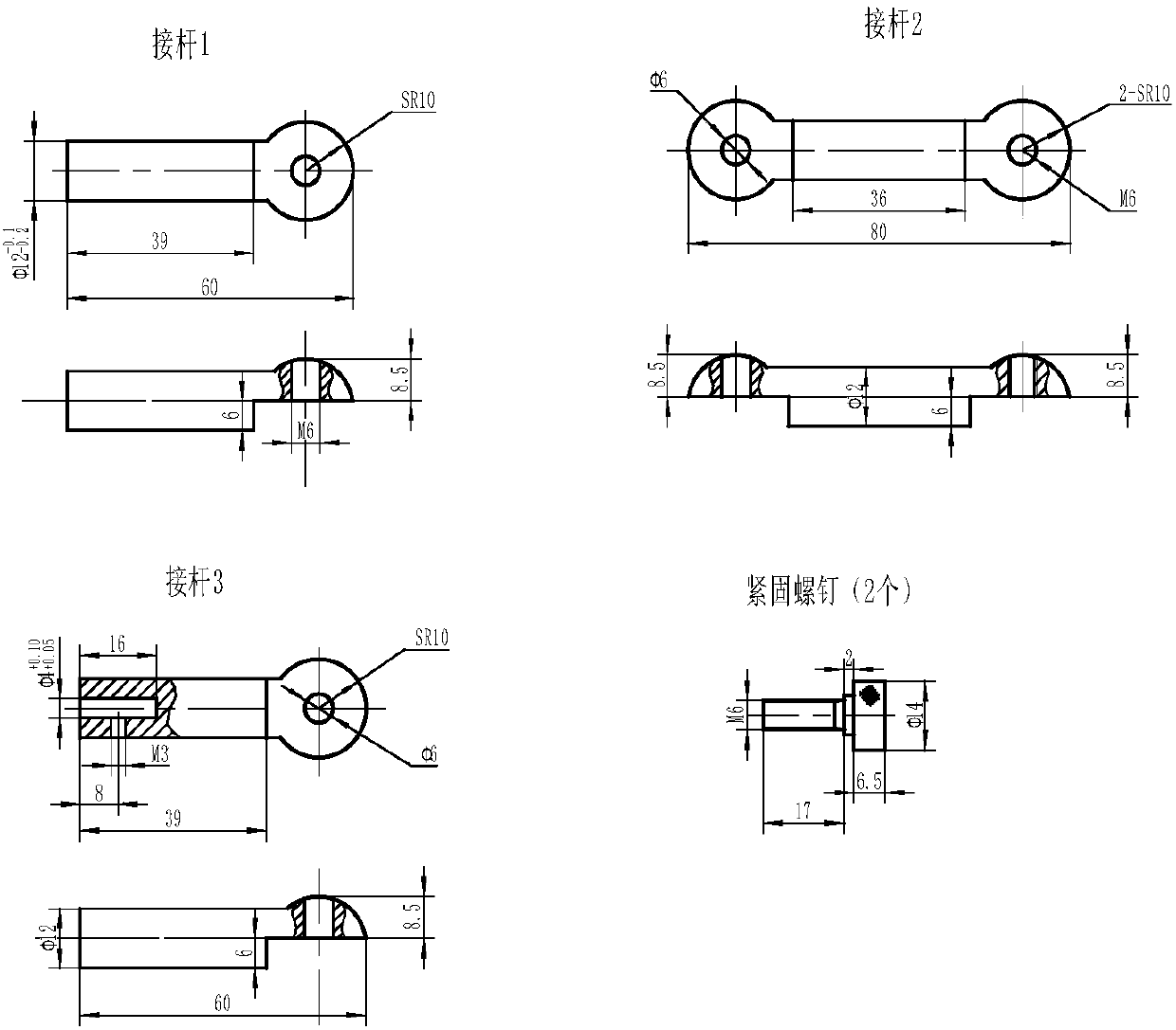
[0037] The present invention provides a three-bar connecting device for robot tool coordinate system measurement, which includes a connecting rod 1, an adapter rod 2, and a meter connecting rod 3, and a three-bar connecting device with two joints composed of a lever dial indicator 4 measuring device.

[0038] One end of the connecting rod 1 is connected to the reserved installation hole of the robot flange through a threaded structure, and the other end is connected to the connecting rod 2 through the connecting bolt 5. After manually adjusting the rotation angle, the fixed position is locked, and it is the connecting piece on the first joint of the whole device. Form the first rotational degree of freedom.

[0039] One end of the adapter rod 2 is connected to the connecting rod 1 through the fastening screw 5, and the other end is connected to the connecting rod 3 through the fastening screw 6. After manually adjusting the rotation angle, the fixed position is locked, and it ...

Embodiment 2

[0044] The present invention also provides a three-bar device and method for measuring the robot tool coordinate system, which includes the following steps:

[0045] The first step is to connect the connecting rod 1 of the assembled three-bar device with the mounting hole of the robot hand flange through threads.

[0046] The second step is to adjust the rotation angle of the connecting rod 2 and the table connecting rod 3 to reach the required measurement position, and lock the connecting bolt 5 and the connecting bolt 6.


PUM


Abstract

The invention relates to a three-rod type device and method for measuring a robot tool coordinate system. The device comprises a connecting rod, a switching rod and a test indicator connecting rod, wherein the connecting rod is connected to the switching rod; the switching rod is connected to the test indicator connecting rod; the test indicator connecting rod is connected to a test indicator forauxiliary measurement. According to the device for measuring the robot tool coordinate system, 360-degree rotating stepless control of the measurement is realized by a form similar to a mechanical arm, and the adjusting parts are fewer, so that the measurement range is wider; the method provides an auxiliary means for measuring an origin (TCP point) of the tool coordinate system during debugging of an industrial robot, and particularly relates to a method for debugging the origin of the tool coordinate system of the industrial robot without a robot hand tool. The three-rod type device comprises two rotational degrees of freedom and a translation degree of freedom, the dial indicator is arranged at the tail end for auxiliary measurement, and through the adoption of the debugging measurementmethod, a structural connection end adopts a spherical shape, so that the device is attractive and concise, easy to install, low in cost and convenient to adjust.

Description

technical field [0001] The invention relates to a three-bar type device and method for measuring a tool coordinate system in the early stage of application and debugging of an industrial robot, belonging to the field of mechanical engineering and industrial automation, in particular to the application field of industrial robots. Background technique [0002] Before the industrial robot is put into normal work, in addition to the zero position of each axis that needs to be corrected, the tool coordinate system also needs to be measured. The measurement method is usually to manually move the robot to change the attitude of the work space around the origin of the tool coordinate system (that is, the TCP point). [0003] The Chinese invention patent with the publication number CN201410179964.7 discloses a method for measuring the coordinate system of a robot tool that is common in the prior art. This robot tool coordinate system measurement is used for industrial robots with han...

Claims


Application Information

Patent Timeline
IPC IPC(8): G01B5/004
CPCG01B5/004
Inventor 田宏宇余旭陈树君李方刘伟刘冰冰
Owner BEIJING UNION UNIVERSITY
Why Eureka
Try Eureka