Eureka AIR delivers breakthrough ideas for toughest innovation challenges, trusted by R&D personnel around the world.

Rope winch

Active Publication Date: 2017-10-10
LIEBHERR COMPONENTS BIBERACH GMBH
View PDF68 Cites 19 Cited by
  • Summary
  • Abstract
  • Description
  • Claims
  • Application Information

AI Technical Summary

Benefits of technology

The present invention aims to improve hoisting winches by solving problems with previous designs. It helps prevent issues like windinb difficulties and excessive equipment size and weight. Additionally, a detection device can be added to detect the position of the cable and help the controller of the hoisting winch reduce the speed of the hoisting drum to prevent wear on the cable.

Problems solved by technology

However, the cable lengths which can be wound up are ultimately also limited here since with correspondingly higher cable lengths a larger number of divisions would have to be carried out, which would in turn, however, result in drum lengths and drum widths which are too large in which the run-in angle of the cable, which becomes more and more oblique in the lateral part winding regions toward the end-side face of the hoisting drum, would result in transverse forces on the cable winding which are larger and larger.

Method used


Image

  • Rope winch
  • Rope winch
  • Rope winch

Examples


Embodiment Construction

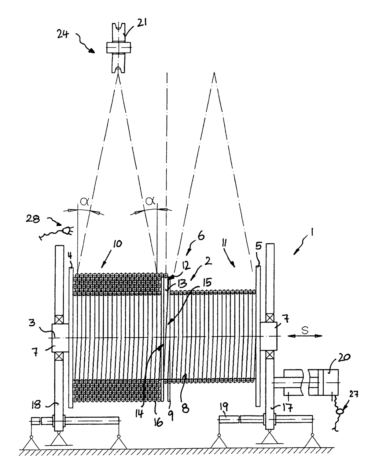
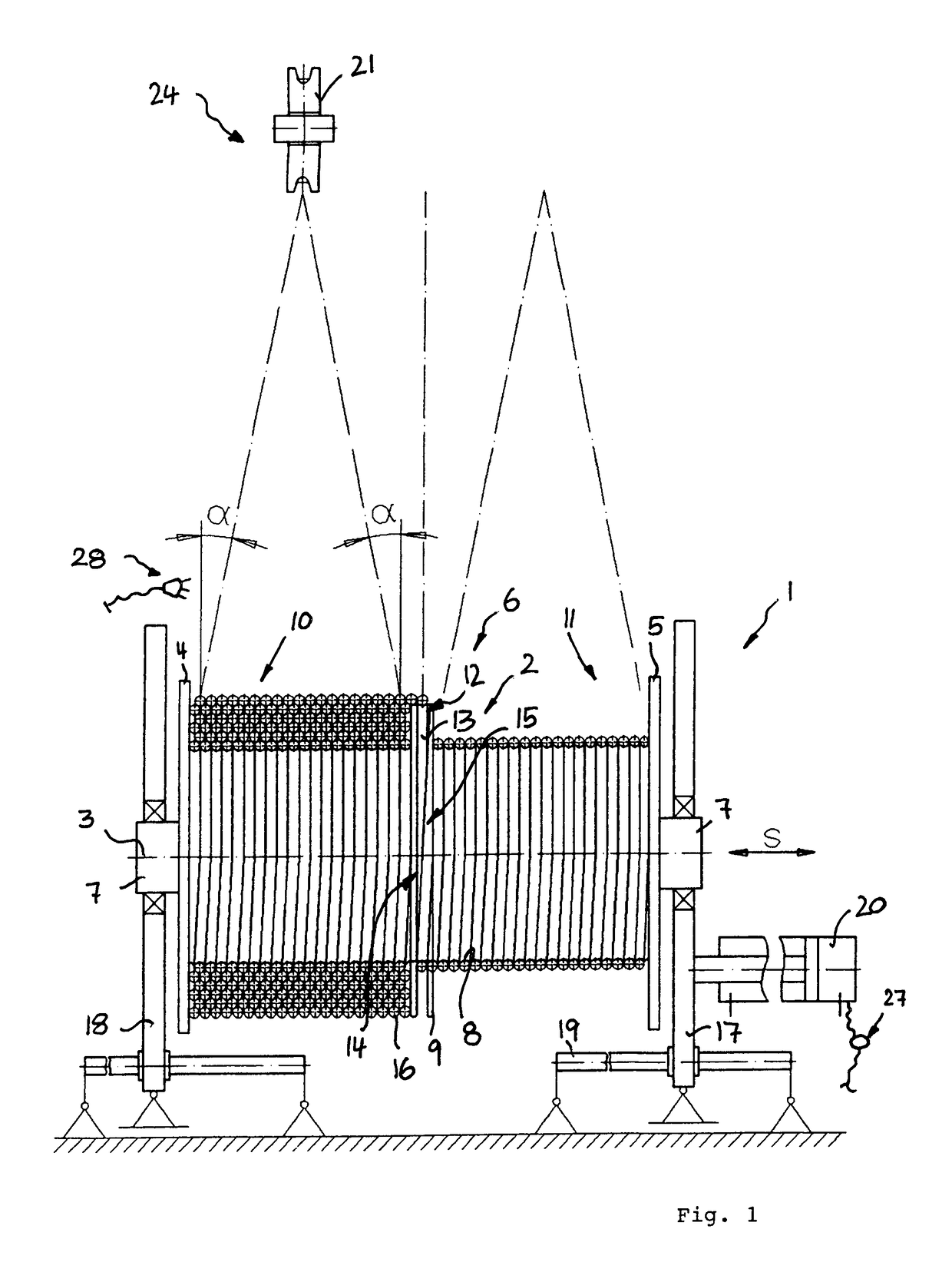
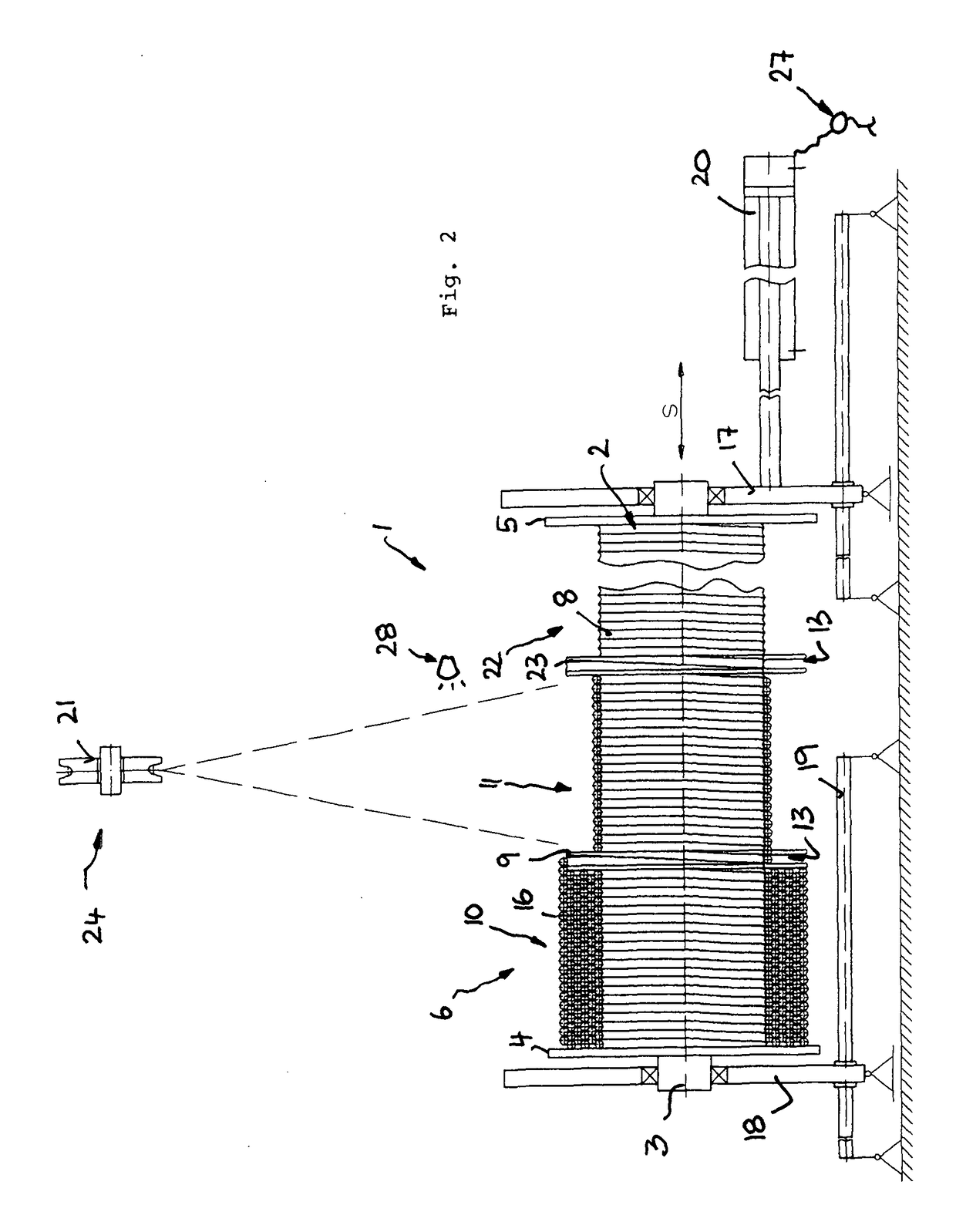
[0042]The hoisting winch 1 shown in the Figures comprises a substantially cylindrical hoisting drum 2 at whose end faces two flanged wheels 4 and 5 are provided which extend radially to the axis of rotation 3 of the hoisting drum and between which the winding region 6 of the hoisting drum 2 is defined. In a manner known per se, bearing and / or drive stubs 7 in the form of axially projecting shaft stumps can be provided at the hoisting drum 2 and the hoisting winch 1 can be installed with them in the hoisting gear of a crane or the like and can be longitudinally supported as will be explained below.

[0043]The jacket surface of the hoisting drum 2 is, as FIG. 1 shows, provided with cable grooves 8 which extend spirally in the manner of a thread on the outer side of the hoisting drum 2 to guide the cable to be wound up, more precisely the first cable layer, on the hoisting drum 2.

[0044]As FIG. 1 shows, the winding region 6 of the hoisting drum 2 is divided into two part winding regions 1...


PUM


Abstract

The present invention relates to a hoisting winch, in particular to a hoisting gear winch, having a hoisting drum whose winding region is bounded by two lateral flanged wheels, wherein at least one further flanged wheel is provided between the lateral flanged wheels for dividing the winding region into at least two part winding regions, wherein the cable can be guided beyond the named further flanged wheel into the at least two part winding regions. It is suggested in accordance with the invention to move the hoisting drum and / or a transverse cable guide arranged in front of the hoisting drum transversely to the longitudinal direction of the running in / running off cable approximately in the longitudinal direction of the drum and / or to adjust the angular position of the hoisting drum transversely to the longitudinal direction of the drum with respect to at least one transverse axis.

Description

BACKGROUND OF THE INVENTION[0001]The present invention relates to a hoisting winch, in particular to a hoisting gear winch, having a hoisting drum whose winding region is bounded by two lateral flanged wheels, wherein at least one further flanged wheel is provided between the lateral flanged wheels for dividing the winding region into at least two part winding regions, wherein the cable can be guided beyond the named further flanged wheel into the at least two part winding regions.[0002]Winding problems typically occur in hoisting winches when the hoisting drum has a very large number of turns next to one another and the cable is to be wound in a plurality of layers over one another. The problem is in particular intensified in this respect when the cable is to be wound up without any or with only a little cable preload. If higher cable tension forces abruptly act on a more or less loosely wound cable package such as can occur, for example, during demolition work or dismantling work,...

Claims


Application Information

Patent Timeline
IPC IPC(8): B66D1/39B66D1/38B66D1/36B66D1/26B66D1/30
CPCB66D1/39B66D1/26B66D1/38B66D1/365B66D1/30
Inventor HAUSLADEN, NORBERTHEPP, GERD
Owner LIEBHERR COMPONENTS BIBERACH GMBH
Why Eureka
Eureka Blog
Learn More