
Instrument-mounted tension sensing mechanism for robotically-driven medical instruments

a technology of tension sensing mechanism and robotic drive, which is applied in the field of surgical robotics, can solve problems such as control problems, engineering challenges that require creative engineering workarounds, and robotically controlled technologies, and achieve the effect of low friction

Active Publication Date: 2017-10-17
AURIS HEALTH INC
View PDF97 Cites 244 Cited by
  • Summary
  • Abstract
  • Description
  • Claims
  • Application Information

AI Technical Summary

Benefits of technology

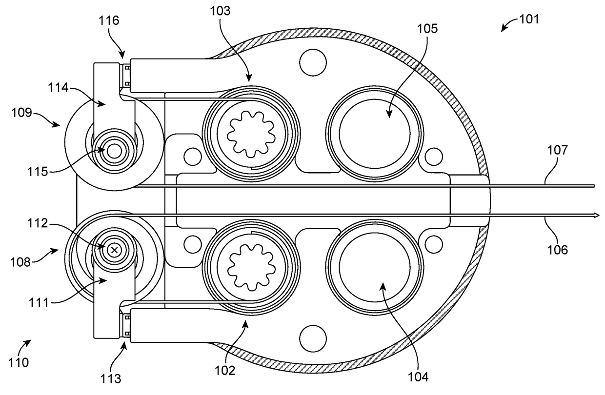
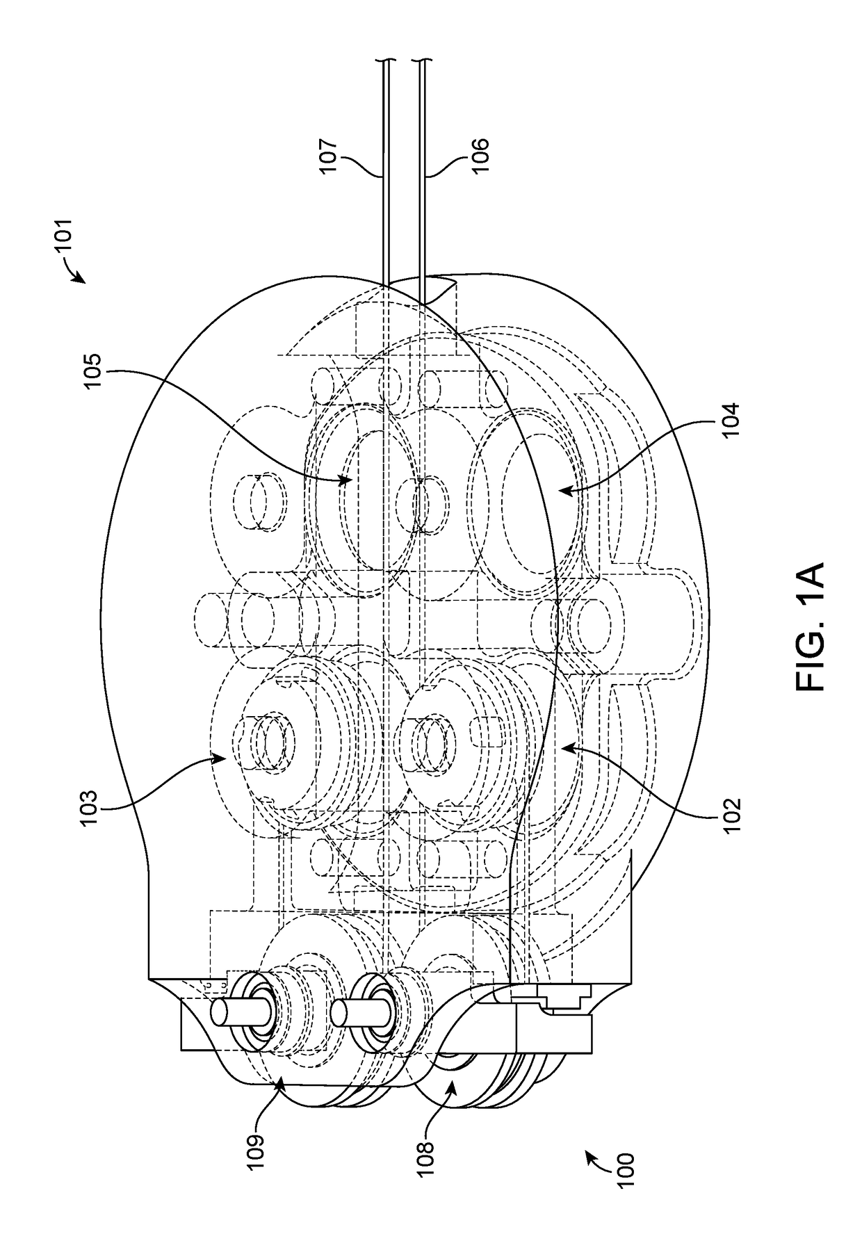
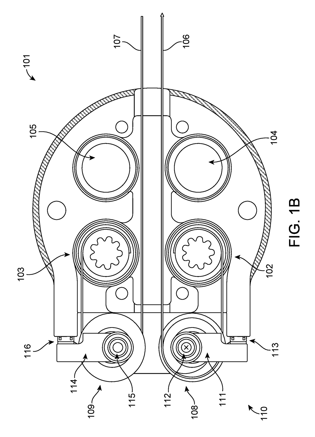
The present invention is a medical device that has a distal end that can be actuated by tension in the elongated member. The device includes a base that redirects the elongated member, and a lever element that exerts a reactive force on a sensor in response to tension in the elongated member. The lever element is constrained by a pivot point and a sensor. The device is flexible and can be used with a robotic drive mechanism. The ratio of tension in the elongated member to the reactive force on the sensor is fixed. The device includes a load cell, piezoresistive device, piezoelectric device, and strain gauge as the sensor.

Problems solved by technology

Robotically-controlled technologies, however, sometimes create engineering challenges that require creative engineering workarounds.
In the case of robotically-controlled tools, the use of actuation tendons to operate robotic laparoscopic tools and catheters gives rise to control problems that often requires very precise monitoring of the actuation tendons.

Method used


Image

  • Instrument-mounted tension sensing mechanism for robotically-driven medical instruments
  • Instrument-mounted tension sensing mechanism for robotically-driven medical instruments
  • Instrument-mounted tension sensing mechanism for robotically-driven medical instruments

Examples


Embodiment Construction

[0022]Although certain preferred embodiments and examples are disclosed below, inventive subject matter extends beyond the specifically disclosed embodiments to other alternative embodiments and / or uses, and to modifications and equivalents thereof. Thus, the scope of the claims appended hereto is not limited by any of the particular embodiments described below. For example, in any method or process disclosed herein, the acts or operations of the method or process may be performed in any suitable sequence and are not necessarily limited to any particular disclosed sequence. Various operations may be described as multiple discrete operations in turn, in a manner that may be helpful in understanding certain embodiments; however, the order of description should not be construed to imply that these operations are order dependent. Additionally, the structures, systems, and / or devices described herein may be embodied as integrated components or as separate components.

[0023]To guarantee co...


PUM

PropertyMeasurementUnit
takeoff angleaaaaaaaaaa
tensionaaaaaaaaaa
frictionaaaaaaaaaa

Abstract

A tension mechanism for a robotically-controlled medical device measures the tension applied to an actuation tendon to provide feedback to a robotic controller. In one embodiment, the device comprises an elongated instrument, an elongated member, and a base. The elongated member is coupled to the distal end of the elongated instrument, configured to actuate the distal end of the elongated instrument in response to tension in the elongated member. The base is located at the proximal end of the elongated instrument, and comprises a first redirect surface that redirects the elongated member. The first redirect surface is coupled to a lever element that is configured to exert a reactive force on a sensor in response to tension in the elongated member.

Description

CROSS-REFERENCE TO RELATED APPLICATIONS[0001]This application claims the benefit of and priority to U.S. Provisional Application No. 62 / 184,741 filed Jun. 25, 2015, the entire contents of which are incorporated herein by reference. This application is related to U.S. patent application Ser. No. 14 / 523,760, filed Oct. 24, 2014, U.S. Provisional Patent Application No. 62 / 019,816, filed Jul. 1, 2014, U.S. Provisional Patent Application No. 62 / 037,520, filed Aug. 14, 2014, U.S. Provisional Patent Application No. 62 / 057,936, filed Sep. 30, 2014, and U.S. Provisional Patent Application No. 62 / 140,344, filed Mar. 30, 2015, the entire contents of which are incorporated herein by reference.BACKGROUND[0002]1. Field of Art[0003]This description generally relates to surgical robotics, and particularly to an instrument-mounted tension sensing design that may be used in conjunction with a medical robotics platform for a number of surgical procedures. More particularly, the field of the invention ...

Claims


Application Information

Patent Timeline
Patent Type & Authority Patents(United States)
IPC IPC(8): A61B34/30A61M25/01A61B5/00G01L5/04
CPCA61B34/30A61B5/4523A61B5/6852A61M25/0147A61B2034/301A61B2562/0252A61B2562/0261G01L5/04A61B2034/715
Inventor SCHUH, TRAVIS
Owner AURIS HEALTH INC
Learn More