Handling device and method for handling drill string components in rock drilling and rock drill rig

a technology for handling devices and drill rigs, which is applied in drilling rods, drilling accessories, earthwork drilling and mining, etc., and can solve problems such as failure to thread, not negligible risk of operator being subject to lifting and clamping injuries, and not tolerating alignment deviations

Active Publication Date: 2017-10-17
EPIROC AB
View PDF30 Cites 10 Cited by
  • Summary
  • Abstract
  • Description
  • Claims
  • Application Information

AI Technical Summary

Benefits of technology

[0015]In order to effectively and safely ensure accurate alignment between the gripper unit and the drill string component being supported by the swing arm, according to the invention, a guiding beam is arranged which forms mechanical stops for the gripper unit in said second position as well as for the swing arm in the delivering position. For this purpose, the guiding beam is fastenable at its end regions in connection with the respective regions of the first and second axes. This arrangement results in that the guiding beam in each adjustment position of a drill rig, for example with different inclinations of the feed beam, with varying inclination of a support for the rig, and different vertical positions of the parts of the rig, more or less automatically can provide on the one hand setting references through said mechanicals stops, on the other hand more or less automatically also provide suitable end positioning of the drill string component being carried by the swing arm in respect of the gripper unit.

Problems solved by technology

These working steps are stressful and brings about a not negligible risk of being subject to lifting and clamping injuries for the operator.
Core drilling is often performed to very great depths, such as for example to drill length between 1000-2000 m. Because of the drill bit in operation being subjected to wear, it has to be exchanged relatively often, which results in that the entire drill string has to be lifted out from the drill hole, be dismounted into drill string components, the worn drill bit be removed and be replaced by a new one, whereupon the drill string can again be lowered down into the hole.
Thus is not tolerated an alignment deviation of components to be threaded together of more than 1°.
Greater angular deviations most likely results in failing threading and in more serious cases to thread damage.

Method used


Image

  • Handling device and method for handling drill string components in rock drilling and rock drill rig
  • Handling device and method for handling drill string components in rock drilling and rock drill rig
  • Handling device and method for handling drill string components in rock drilling and rock drill rig

Examples


Embodiment Construction

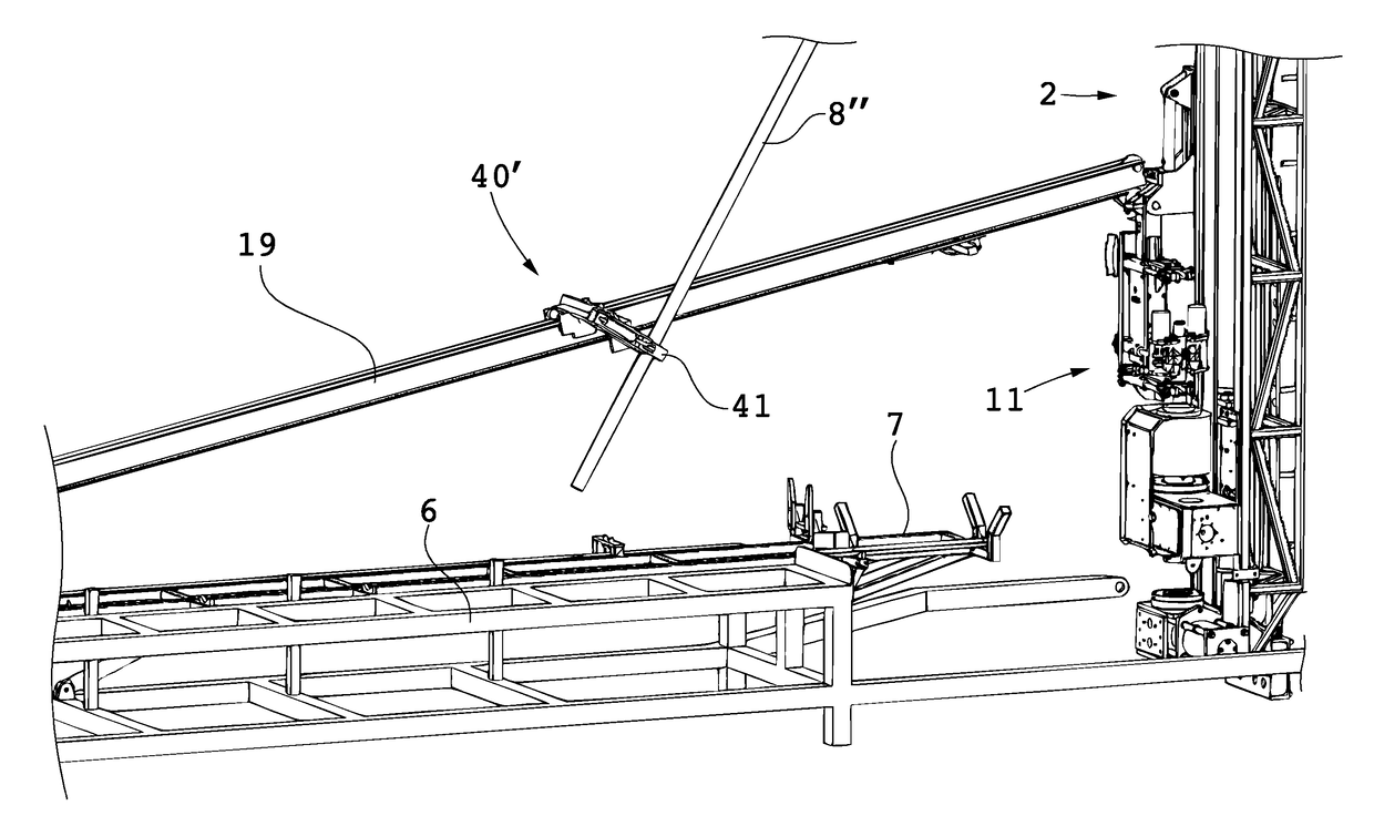
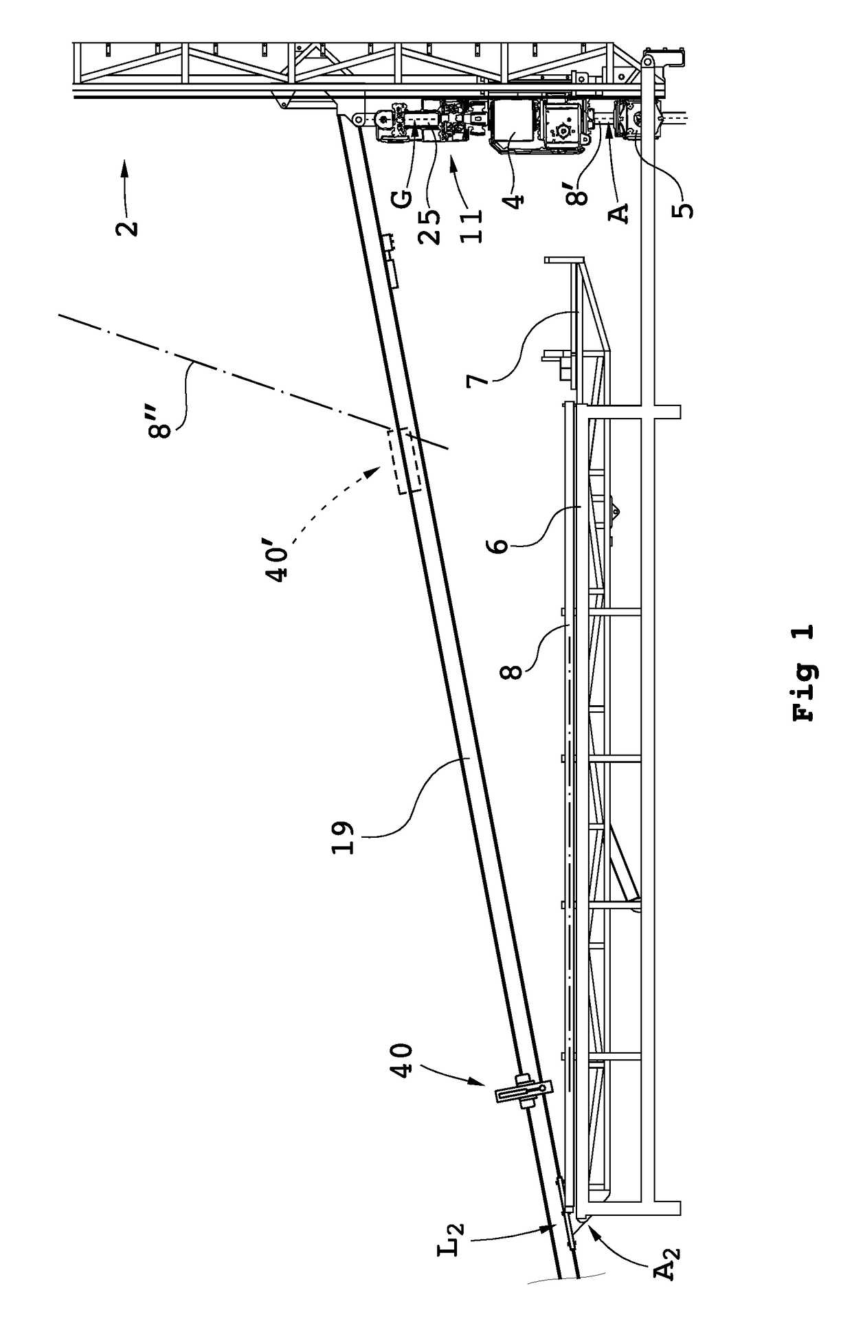
[0037]FIG. 1 shows a feed beam 2 of a rock drill rig for core drilling being adjustable in different angles. The rig includes a rotator device 4, which is supported on the feed beam 2 for movement to and fro. Below (in the Figure) the rotator device 4 is arranged a tube holder 5 for temporary holding the drill string when this is required.

[0038]Beside the feed beam 2 is arranged a (not shown) power and driving aggregate for proving pressure fluid etc to the rock drill rig and a lifting winch (not shown). A magazine 6 is arranged for receiving drill string components (indicated with interrupted line at 8), to be brought into respectively taken out from the rock drill rig in a manner will be described below.

[0039]The magazine 6 can be constructed in various manners but is in FIG. 1 exemplified in the form of a generally horizontal table, which is tiltable such that drill string components 8 can be brought to roll towards a swing arm 7 for reception of drill string components 8.

[0040]I...


PUM


Abstract

A handling device for handling drill string components with respect to a rock drill rig including a rotator device supported on a feed beam and arranged to rotate and drive a drill string component. A gripper grips drill string components. The gripper is swingably supported around a first swing axis between: a first position aligned with the active drill string position, and a second position aligned with a delivering position for drill string components. A swing arm includes a support configured to support a drill string component and is swingable around a second swing axis. A guiding beam is fastenable at end regions in connection with respective regions of the first and second swing axis. The guiding beam forms mechanical stops for the gripper in the second position and for the swing arm in the delivering position. Also, a rock drill rig and a method.

Description

CROSS-REFERENCE TO RELATED APPLICATIONS[0001]This application claims priority to Swedish patent application 1250728-1 filed 28 Jun. 2012 and is the national phase under 35 U.S.C. §371 of PCT / SE2013 / 050761 filed 25 Jun. 2013.FIELD OF THE INVENTION[0002]The invention concerns a handling device for handling drill string components in respect of a drill rig, wherein the handling device includes a gripper unit for gripping drill string components to be placed into or be removed from an active drill string position (A) of the drill rig. The invention also relates to a corresponding method and a rock drill rig equipped with such a handling device.BACKGROUND OF THE INVENTION[0003]Core drilling for exploration purposes is usually performed with rock drill rigs, wherein the drill string components are placed in the active drill string position, lifted up from or lowered down in the drill hole with the aid of a winch. The winch wire is fastened to the uppermost drill string component with the ...

Claims


Application Information

Patent Timeline
Patent Type & Authority Patents(United States)
IPC IPC(8): E21B19/15E21B19/20
CPCE21B19/155E21B19/20
Inventor GUSTAVSSON, RICKARD
Owner EPIROC AB
Why Eureka
Try Eureka