Display device

a display device and display technology, applied in the field of electronic devices, can solve problems such as inconvenient us

Active Publication Date: 2017-10-17
E INK HLDG INC
View PDF15 Cites 3 Cited by
  • Summary
  • Abstract
  • Description
  • Claims
  • Application Information

AI Technical Summary

Benefits of technology

[0018]Accordingly, due to having the first light source module, the display panel and the transparent filling, the display device provided by embodiments of the invention allows the first light beam provided by the first light source module to effectively serve as the light source of the display panel, so that the image frame displayed by the display panel is clearly presented. In another aspect, since the display device provided by embodiments of the invention has the first light source module, the second light source module and the display panel, a good double-sided display effect is presented through the matching of double-sided light emission.

Problems solved by technology

However, when there is no assistance from environmental light source, the image frames presented by the transparent displays often cannot be read by users, thereby causing inconvenience in usage.

Method used


Image

  • Display device
  • Display device
  • Display device

Examples


first embodiment

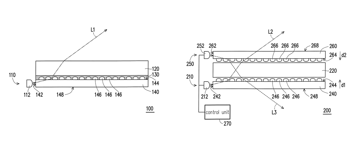
[0026]Therefore, since the display device 100 of the invention includes the first light source module 110, the display panel 120 and the transparent filling 130, through such configuration and optical properties thereof, the first light beam L1 provided by the first light source module 110 is effectively transmitted to the display panel 120 and becomes an image frame, thereby allowing a user to view a good image.

[0027]More specifically, referring to FIG. 1, in the embodiment, the first light-emitting surface 144 has a plurality of optical microstructures 146, wherein the optical microstructures 146 are formed at the first light-emitting surface 144 to destroy the total reflection phenomenon of the first light beam L1 emitted by the first light source 112. In other words, after the first light beam L1 emitted by the first light source 112 enters the first LGP 140, as long as the first light beam L1 is transmitted to the first light-emitting surface 144, the optical microstructures 14...

third embodiment

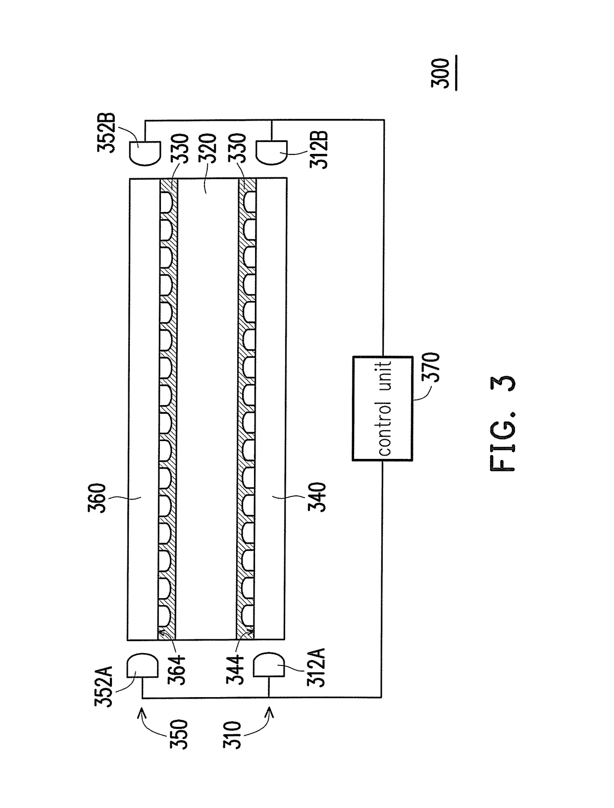
[0034]FIG. 3 is a cross-sectional view of a display device according to the invention. Referring to FIG. 3, a display device 300 is generally similar to the display device 200, wherein a main difference between the two is that: in this embodiment, the display device 300 further includes a transparent filling 330 disposed between a first light guide plate (LGP) 340 and a display panel 320 and between a second light guide plate (LGP) 360 and the display panel 320, and the transparent filling 330 connects the display panel 320 to a first light-emitting surface 344 and a second light-emitting surface 364. The refractive index of the transparent filling 330 is smaller than the refractive index of the first LGP 340 and the second LGP 360, and smaller than or equal to the refractive index of a surface material of the display panel 320. In other words, through configuration of the transparent filling 330 and optical properties thereof, light beams emitted by first light sources 312A and 312...


PUM


Abstract

A display device includes a first light source module, a display panel and a transparent filling. The first light source module includes at least one first light source and a first light guide plate (LGP). The first LGP includes a first light-incident surface and a first light-emitting surface. The first light-emitting surface connects the first light-incident surface. The display panel is disposed adjacent to the first LGP. The transparent filling connects the display panel and the first light-emitting surface. The refractive index of the transparent filling is smaller than that of the first LGP and smaller than or equal to that of a surface material of the display panel. The first light source emits a first light beam into the first LGP through the first light-incident surface, and the first light beam is emitted from the first light-emitting surface and transmitted to the display panel through the transparent filling.

Description

CROSS-REFERENCE TO RELATED APPLICATION[0001]This application claims the priority benefit of Taiwan application Ser. No. 104105640, filed on Feb. 17, 2015. The entirety of the above-mentioned patent application is hereby incorporated by reference herein and made a part of this specification.BACKGROUND OF THE INVENTION[0002][Field of the Invention][0003]The invention relates to an electronic device and more particularly relates to a display device.[0004][Description of Related Art][0005]A transparent display panel refers to a display panel having a certain degree of transparency and is capable of clearly displaying the background behind the panel, while presenting image frames on both surfaces, providing a double-sided display effect. The transparent display panel is not only suitable, for example, in portable electronic products, such as electronic eyeglasses, but is also suitable for a variety of applications, such as windows in buildings, car windows and shop windows. Besides the o...

Claims


Application Information

Patent Timeline
Patent Type & Authority Patents(United States)
IPC IPC(8): F21V7/04F21V8/00
CPCG02B6/005G02B6/0036G02B6/0076
Inventor SHEI, TSAI-WEIHUANG, HSIN-TAO
Owner E INK HLDG INC
Why Eureka
Try Eureka