
Modal antenna array for interference mitigation

a multi-path mitigation and antenna array technology, applied in the field of wireless communication, can solve problems such as similar congestion in wireless local area networks, and achieve the effect of improving the quality of communication system linkag

Active Publication Date: 2017-10-17
KYOCERA AVX COMPONENTS (SAN DIEGO) INC
View PDF3 Cites 3 Cited by
  • Summary
  • Abstract
  • Description
  • Claims
  • Application Information

AI Technical Summary

Benefits of technology

The patent describes a way to use multiple antennas to create a better array for communication. By using different modes of these antennas, researchers have been able to create patterns that reduce interference and improve the quality of the signal. The patent also describes a way to adjust the patterns created by the antennas to optimize performance. Overall, this technology helps make wireless communication more efficient and reliable.

Problems solved by technology

Similar congestion can be found on wireless local area network (WLAN) networks where a large number of users are putting strain on these systems.

Method used


Image

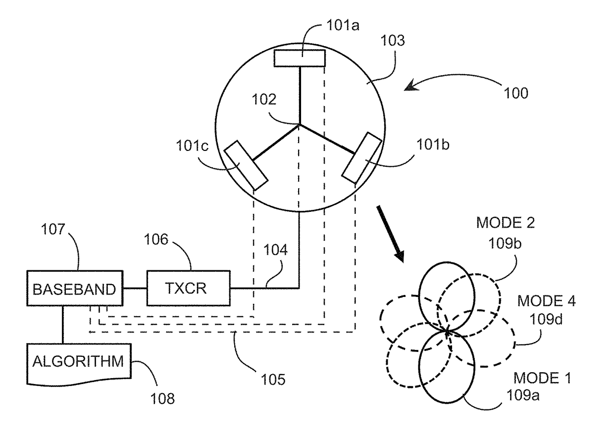
  • Modal antenna array for interference mitigation
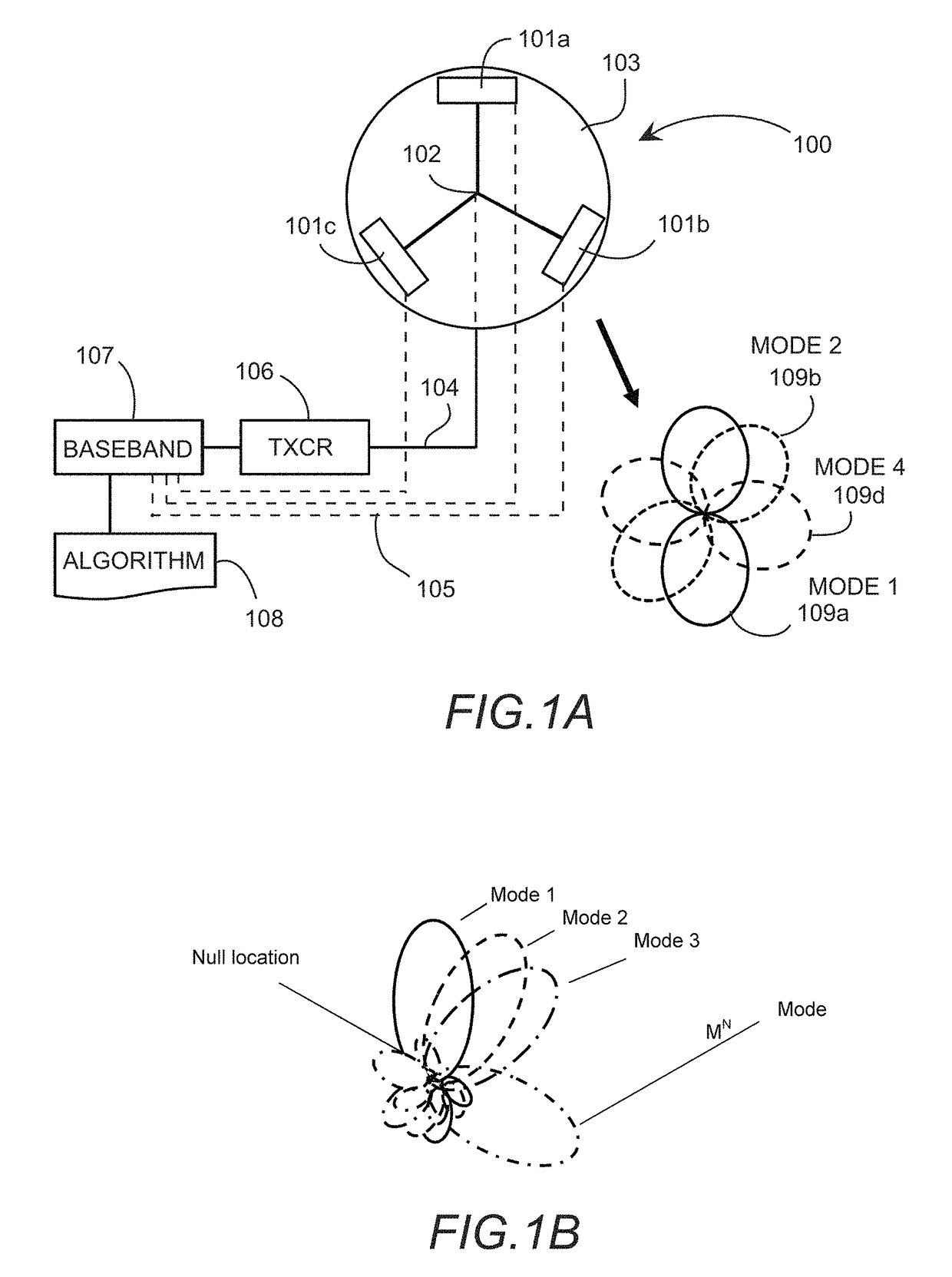
  • Modal antenna array for interference mitigation
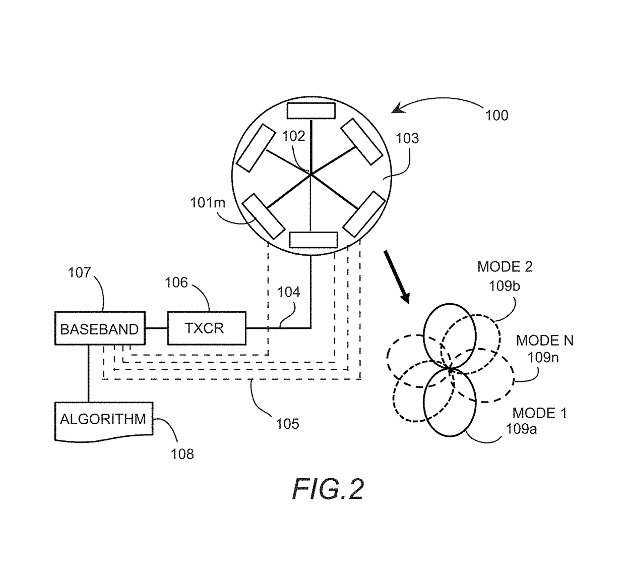
  • Modal antenna array for interference mitigation

Examples


Embodiment Construction

[0022]The following invention describes an antenna array technique that provides better interference and multipath mitigation for communication systems operating in multipath environments and / or in regions where there are large numbers of communication devices operating. The result of implementing this antenna array technique is reduced interference from adjacent mobile communication devices and reduced adverse effects from multipath, with the benefits being higher data rate communication and reduced interruption of service.

[0023]An antenna system comprises an array of Modal antennas, with the array typically formed in a circular fashion. A Modal antenna is a single port antenna system capable of generating multiple radiation modes, wherein the radiation modes are de-correlated when compared to each other. Arraying multiple Modal antennas together can result in an array that has a substantially larger number of individual beam states compared to a traditional antenna array formed fr...


PUM


Abstract

A modal antenna array is described where modal antenna elements capable of generating multiple radiation modes are used to form array radiation patterns. Nulls in the array radiation pattern can be formed and positioned by proper modal antenna element mode selection, with these nulls used to provide interference suppression or mitigation. The shift in array radiation pattern maxima generated by modal element mode selection can be used to improve communication system link quality by optimizing array radiation pattern characteristics. Specifically, a ring or circular array configuration is described where a simplified common feed port can be implemented to feed multiple modal antenna elements used to form the array. A switch can be used to connect or disconnect one modal element from the array, with this feature providing additional unique array beam states. The modal array can be commanded via a look-up table or algorithm.

Description

CROSS-REFERENCE TO RELATED APPLICATIONS[0001]This application claims benefit of priority with U.S. Provisional Ser. No. 62 / 006,687, filed Jun. 2, 2014; the contents of which are hereby incorporated by reference.BACKGROUND[0002]Field of the Invention[0003]This invention relates generally to the field of wireless communication; and more specifically, to communication networks and antenna array techniques for interference suppression and multipath mitigation.[0004]Description of the Related Art[0005]Cellular networks and WLANs (Wireless Local Area Networks) are prevalent in society and have evolved to a level that moderate to high data rate transmissions along with voice communications are stable and reliable over large regions and throughout urban areas. Mobile user devices have progressed to point of providing not only voice communications and low data rate text and email service but also high data rate internet connectivity. Continued adoption of mobile communications systems and in...

Claims


Application Information

Patent Timeline
Patent Type & Authority Patents(United States)
IPC IPC(8): H01Q3/24H01Q3/26
CPCH01Q3/24H01Q3/2605H01Q3/247H01Q3/26H01Q1/246H01Q3/2611H01Q21/29H01Q25/00
Inventor DESCLOS, LAURENTSHAMBLIN, JEFFREYCHIU, LYNNSINGH, ABHISHEK
Owner KYOCERA AVX COMPONENTS (SAN DIEGO) INC
Learn More