Handling device for handling a rotor blade mold for producing a rotor blade of a wind turbine

a technology of a wind turbine and a handling device, which is applied in the field of transportation vehicles, can solve the problems of complicated and expensive, difficult displacement, and previously known solutions

Inactive Publication Date: 2017-10-24
WOBBEN PROPERTIES GMBH
View PDF25 Cites 0 Cited by
  • Summary
  • Abstract
  • Description
  • Claims
  • Application Information

AI Technical Summary

Benefits of technology

[0012]In that arrangement the transport vehicle includes a first wheel set comprising a plurality of wheels for travel on the first rail set and a second wheel set comprising a plurality of wheels for travel on the second rail set. That therefore provides the option of displacement of the transport vehicle and thus a rotor blade mold arranged thereon in two different directions, wherein the use of the rails enables guided transport which avoids any collisions with other fixed articles in the proximity of the transport vehicle. Thus by virtue of the use of a respective wheel set for the corresponding rail set, there is proposed the use of a respective wheel set for each direction. A change in the directions can thus be effected by a change in the wheel set. Accordingly, switching points for changing from one rail set to another are avoided.
[0022]Preferably there is provided a connection coupling for connecting the transport vehicle and / or a rotor blade mold accommodated on the transport vehicle to supply lines for electric power, compressed air, vacuum and / or control data. Such a connection coupling permits displacement of the transport vehicle without coupling to corresponding supply lines so that coupling has to be implemented only in the respectively required working positions. Such a connection coupling also makes it possible to effect recharging of an electric energy storage means for powering the change device. The coupling operation itself is also effected by means of an electric drive which is supplied with power from the accumulator of the vehicle.
[0023]In an embodiment it is proposed that a plurality of wheels are driven by a common drive motor and the drive is effected by means of drive shafts and universal joints. That is proposed in particular for a longitudinal drive. In the case of the transverse drive each driven wheel unit has its own drive, at any event in accordance with an embodiment. The common drive motor therefore drives at least two and preferably four drive shafts which are respectively connected to at least one wheel by way of a universal joint. Thus it is sufficient to provide a drive motor for a plurality of wheels. The drive torque can be distributed to the transport vehicle by way of drive shafts and fed to the respective wheels for driving them. Because the transport vehicle is preferably intended for travel on respective straight, non-curved rail sets, the wheels at any event of a wheel set which are therefore intended to travel on the same rail set can be driven in synchronous relationship. In addition, by virtue of the rail system, it is basically possible to count on all wheels of a wheel set involving the same rolling properties without trouble.
[0025]Preferably there is provided a transmission between the universal joint and the wheel to reduce a high speed of rotation of the drive shaft which is referred to as the shaft speed to a lower speed of rotation of the wheel referred to here as the wheel speed. Accordingly the same transmissions are to be provided, at least in respect of the transmission ratio, for each driven wheel of a wheel set. It is thus possible to achieve synchronous relationship between the wheels, with a common drive. In the case of the described longitudinal drive that synchronous relationship is mechanically imposed. The drive can be effected by a high-speed drive motor and the use of a respective transmission at the respective wheel to be driven permits the use of transmissions of a weaker design. In addition, a transmission ratio provides that a high rotary speed of the drive shafts is also achieved only directly at the wheel and thus the respective drive moment to those faster rotating drive shafts can be kept low, which can lead to a correspondingly weight-saving design configuration both in respect of the drive motor and also the drive shafts. That means that the weight of the transport vehicle overall can be kept correspondingly low. In the case of the described transverse drive the individual drives are electrically coupled and synchronized.
[0029]Preferably the first rail set and / or the second rail set has round rails set into a floor. In particular the first rail set and / or the second rail set are formed by such round rails which are set into a floor. In that case the rails are set into the floor in such a way that in a sectional view with a section transverse relative to the longitudinal direction of the rails in question, a semicircular portion or less of the round rail projects beyond the floor. Thus there is provided a rail system in which only a semi-cylindrical bar or less projects from the floor. Preferably the respective wheels, that is to say the wheels of the first wheel set and the wheels of the second wheel set respectively, are adapted to that convex curvature. Thus the transport vehicle can be guided with its adapted wheels on rails, in particular on rails of a factory floor of a production factory, wherein at the same time those rails barely project out of the floor and further vehicles which are not rail-guided can cross those rails. There is also less injury potential for people who are moving in the proximity of the rails and in particular crossing them. In particular the risk of someone tripping over the rails is reduced.
[0039]Then the second rotor blade mold is moved to the hinge device by means of the transport vehicle in a second direction, in particular in a transverse direction. The rotor blade mold is now arranged in an attainable proximity for fixing to the hinge device and the process accordingly proposes connecting the second rotor blade mold to the hinge device, in particular in such a way that the hinge device moves in a first substantially vertical movement into at least one receiving means of the second rotor blade mold into a connecting position and locking is effected in that connecting position. That locking can also be such that the movement that the hinge device performed for the connection procedure can initially not be reversed by itself and the rotor blade mold connected in that way can also not slip out of the connection.

Problems solved by technology

It is precisely in relation to unwieldy objects like such a long rotor blade mold, however, that displacement is difficult and caution is required to ensure that the rotor blade mold does not knock by mistake against an article in the factory when being moved.
Such previously known solutions are therefore complicated and expensive and in operation require personnel with a great deal of experience and a high level of attentiveness.

Method used


Image

  • Handling device for handling a rotor blade mold for producing a rotor blade of a wind turbine
  • Handling device for handling a rotor blade mold for producing a rotor blade of a wind turbine
  • Handling device for handling a rotor blade mold for producing a rotor blade of a wind turbine

Examples


Embodiment Construction

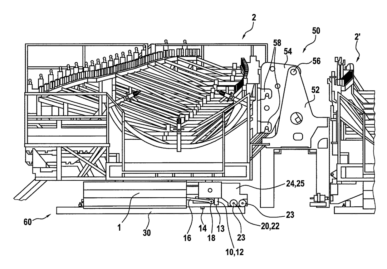
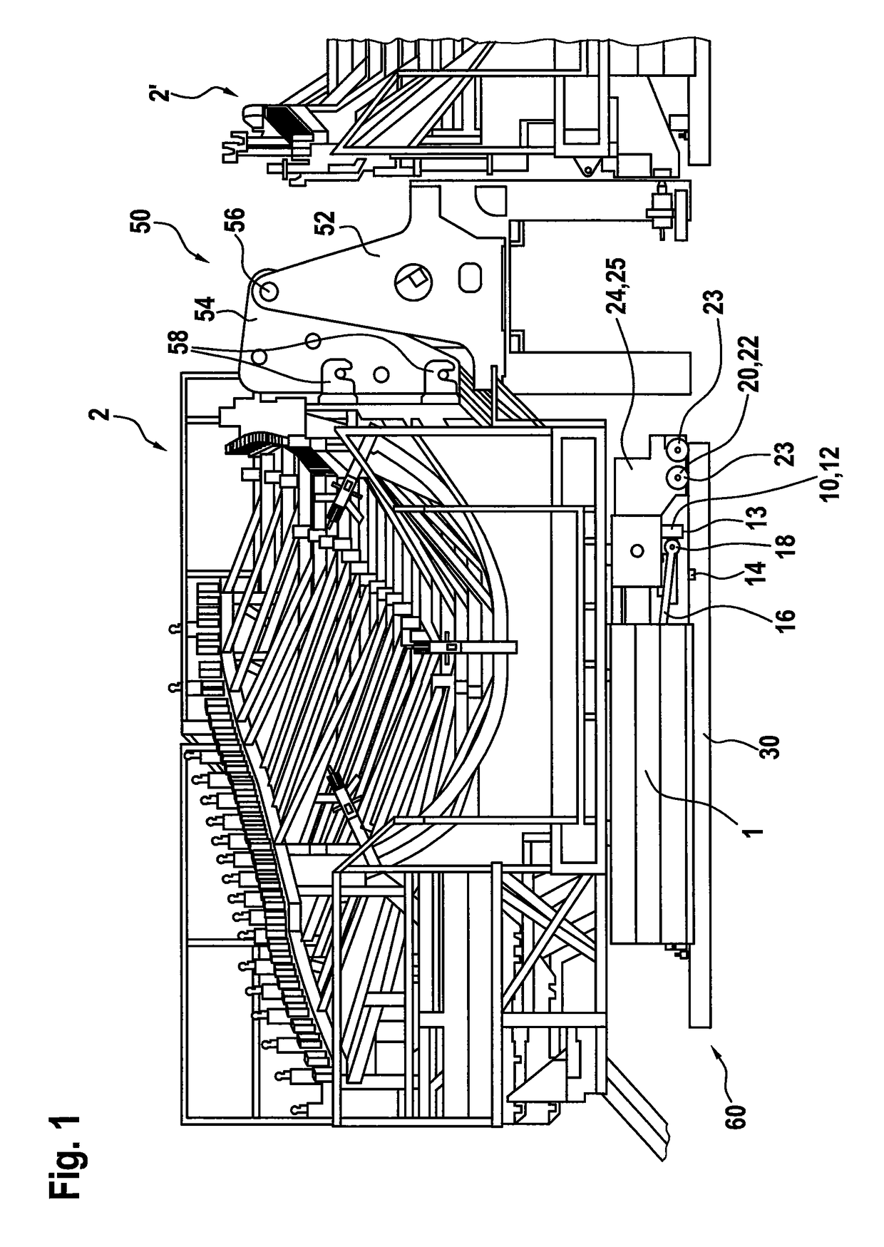
[0051]FIG. 1 shows a perspective view of a transport vehicle 1 with a truss frame structure 2 arranged thereon. The truss frame structure 2 is already roughly adapted to the shape of a rotor blade to be produced and is provided for receiving a rotor blade mold. Such a rotor blade mold is appropriately laid in or placed on that truss frame structure as shown in the drawing. A rotor blade mold provided for the illustrated case is intended for the production of a shell portion of a rotor blade. A further rotor blade mold for a further shell portion would be placed in the truss frame structure 2′ which is only partly shown in FIG. 1. The rotor blade to be produced is finally assembled substantially from those two shell portions. For the sake of simplicity a truss frame structure like the truss frame structure 2 can also be referred to as the mold carrier.

[0052]To fit the two rotor blade shell portions produced in that way together, there is provided a hinge device 50 which has a fixed l...


PUM

PropertyMeasurementUnit
lengthsaaaaaaaaaa
widthaaaaaaaaaa
lengthaaaaaaaaaa

Abstract

The present disclosure concerns a transport vehicle for handling a rotor blade mold for the production of a rotor blade of a wind power installation or a shell portion of a rotor blade of a wind power installation, adapted for use in a handling apparatus. The handling apparatus includes a first rail set for displacement of the transport vehicle in a first direction, and a second rail set for displacement of the transport vehicle in a second direction. In addition the transport vehicle includes a first wheel set including a plurality of wheels for movement on the first rail set, and a second wheel set including a plurality of wheels for movement on the second rail set.

Description

BACKGROUND[0001]Technical Field[0002]The present invention concerns a transport vehicle for handling a rotor blade mold for the production of a rotor blade of a wind power installation. The invention further concerns a handling apparatus which includes such a transport vehicle. Furthermore the invention concerns a process for the production of a rotor blade of a wind power installation.[0003]Description of the Related Art[0004]Wind power installations are generally known and usually require at least one and usually three rotor blades which are to be driven by the wind. Modern wind power installations like for example the one shown in FIG. 1 can have a nominal power of several megawatts and require suitably large rotor blades for that purpose. Such rotor blades can nowadays already be of lengths of about 50 m and more. In that respect such a rotor blade is frequently made, at least in a large portion thereof, from glass fiber-reinforced plastic or similar material. A common possible ...

Claims


Application Information

Patent Timeline
Patent Type & Authority Patents(United States)
IPC IPC(8): B29C33/34B65G67/30B29C31/00B60P1/28B61J1/10B29D99/00
CPCB29C31/006B60P1/28B65G67/30B65G2207/14B29D99/0028B61J1/10B65G2201/02B29C33/34Y02P70/50Y02E10/72B29C31/00
Inventor GEORGS, ARNOBIEBL, HERBERTSCHLUETER, RAINER
Owner WOBBEN PROPERTIES GMBH
Why Eureka
Try Eureka