
Shock detector systems

a technology of shock detectors and detectors, applied in the direction of alarms, instruments, etc., can solve the problems of electrocution of swimmers, injuring or killing people, hazardous water conditions,

Active Publication Date: 2017-10-24
SHOCK ALERT LLC
View PDF24 Cites 4 Cited by
  • Summary
  • Abstract
  • Description
  • Claims
  • Application Information

AI Technical Summary

Benefits of technology

The patent describes a system that uses shock detectors to detect harmful electrical conditions in a body of water. The detectors can activate either a warning alarm or a caution alarm, depending on the severity of the condition. The system also includes a self-test feature to ensure the detectors are working properly. The technical effect of this system is that it provides a way to alert people to potentially harmful water conditions and help locate the source of an electrical short.

Problems solved by technology

One of the problems that occur with an electrical fault in a body of water is that the current leakage into the body of water from the electrical fault can injure or kill a person through electrocution, which is often referred to as electric shock drowning.
Typically, the current leakage occurs from a faulty electrical connection on a boat or dock although other sources may create a hazardous water condition.
If the voltage gradient is sufficiently high the current flowing through the swimmer's body can electrocute the swimmer.
In still other cases a person may be electrocuted if he or she comes into incidental contact with a body of water, which has leakage from an electrical source.
Another problem with harmful electrical conditions in a body of water, such as harmful voltage or harmful current conditions that may injure or kill a person, is that the harmful electrical conditions may be localized in the body of water so that one portion of the body of water contains a harmful electrical condition while another portion of the same body of water does not contain the harmful electrical condition.
That is, the harmful electrical condition is dependent on various conditions including any underwater structures.
As a result one may not be alerted to a nearby presence of the harmful electrical condition until one is within the field of the harmful electrical condition.

Method used


Image

  • Shock detector systems
  • Shock detector systems
  • Shock detector systems

Examples


Embodiment Construction

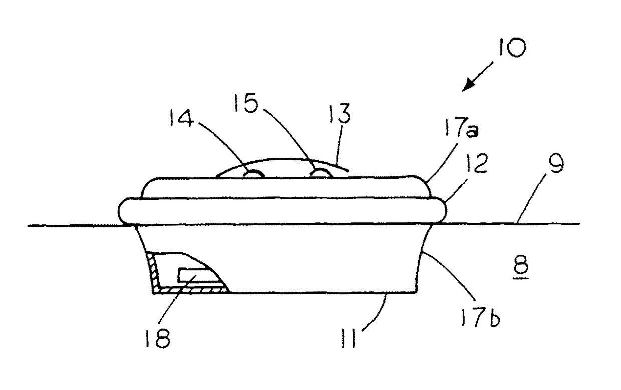
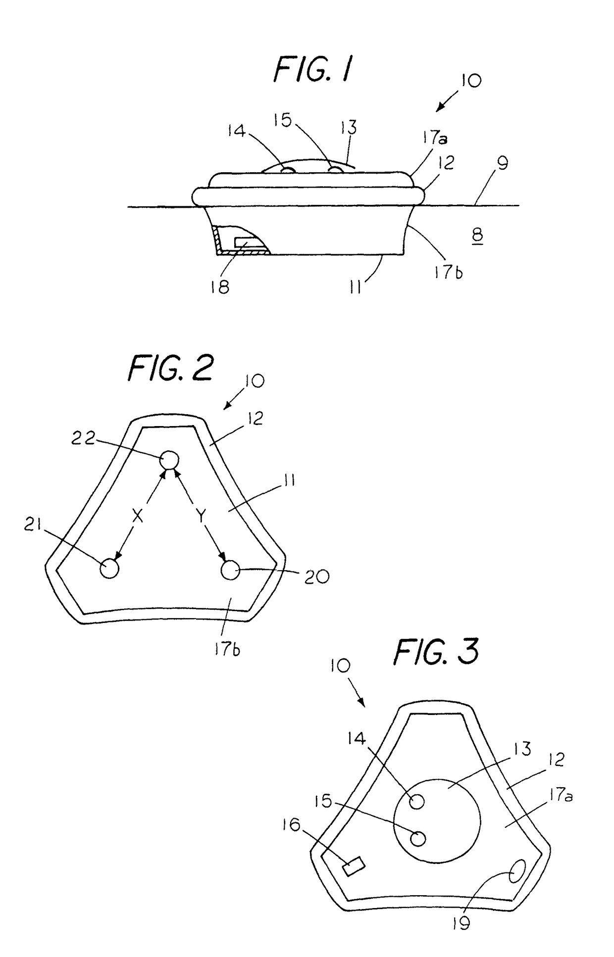
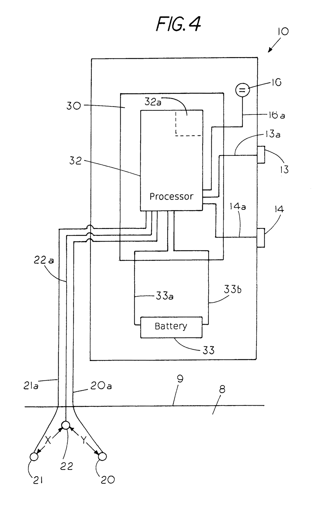
[0021]FIG. 1 shows a free floating, buoyant, open water shock detector 10 floating upright in a body of water 8 having a water line 9 with the upper housing 17a of shock detector 10 including a resilient bumper 12 located around the outer perimeter of the shock detector. The resilient bumper, which is shown located above the water line 9, protects the shock detector in the event the shock detector accidently bumps into an object while floating in the body of water. In this example, the shock detector 10 includes a transparent or see through hemispherical shaped dome 13 extending from a top housing 17a, with a green LED light 13 and a red LED light 14 that are both visible from afar through the transparent dome 13. The lower housing 17b of shock detector 10, which is below the water line 9, is shown partially cut away to reveal a ballast 18 in the bottom of shock detector 10. A feature of the invention is the use of a ballast in the bottom of the floating shock detector that causes t...


PUM


Abstract

A shock detector system for determining the existence of a harmful electrical condition in a body of water proximate a first shock detector or a second shock detector with the first shock detector providing a danger signal if the harmful electrical condition proximate the first shock detector could injure or kill a person coming into contact with the body of water proximate the first shock detector and the second shock detector providing a caution signal if there is no harmful electrical condition detected by the second shock detector even though there is a harmful electrical condition proximate the first shock detector.

Description

CROSS REFERENCE TO RELATED APPLICATIONS[0001]This application is a continuation in part of application Ser. No. 14 / 999,165 filed Apr. 5, 2016 titled Shock Detector (pending), which is a continuation in part of application Ser. No. 14 / 998,497 filed Jan. 12, 2016 (pending), which is a continuation of application Ser. No. 13 / 987,731 filed Aug. 26, 2013 (now U.S. Pat. No. 9,285,396), which claim priority to provisional application Ser. No. 61 / 743,184 filed Aug. 28, 2012; this application is also a continuation in part of application Ser. No. 15 / 165,371 filed May 26, 2016 (pending), which is a continuation of application Ser. No. 13 / 987,731 filed Aug. 26, 2013 (now U.S. Pat. No. 9,285,396).STATEMENT REGARDING FEDERALLY SPONSORED RESEARCH OR DEVELOPMENT[0002]NoneREFERENCE TO A MICROFICHE APPENDIX[0003]NoneBACKGROUND OF THE INVENTION[0004]One of the problems that occur with an electrical fault in a body of water is that the current leakage into the body of water from the electrical fault c...

Claims


Application Information

Patent Timeline
Patent Type & Authority Patents(United States)
IPC IPC(8): G08B21/00G08B21/08
CPCG08B21/082G08B21/02
Inventor KING, JR., L. HERBERTKEEVEN, JAMESVLASATY, FRANKHILL, ANDREW
Owner SHOCK ALERT LLC
Learn More